MTR3000 Third Party Controllers: Community Repeater Panel E-5
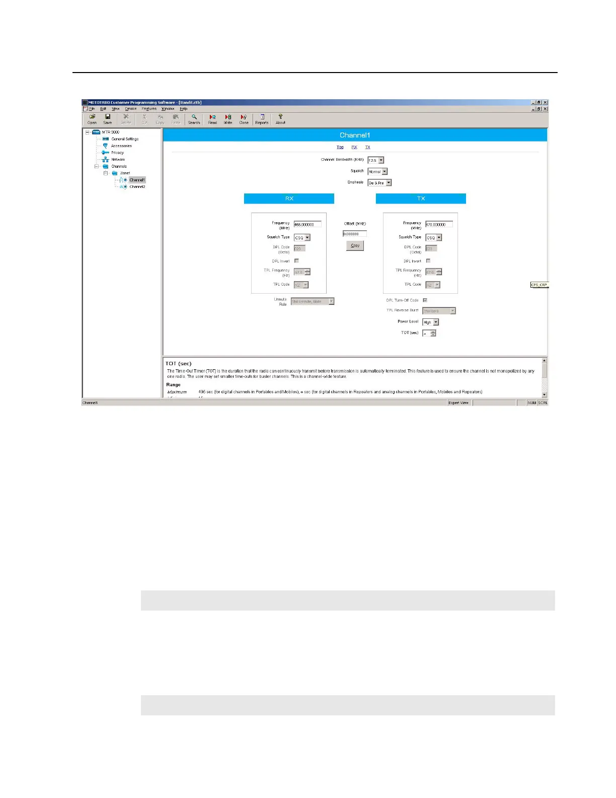
Figure E-5 CPS Configuration for Community Repeater Panel (2 of 2)
E.2.5 Community Repeater Panel Settings
The input and output levels should be adjusted per the community repeater panel’s instructions. The
summary below gives a brief overview of the high level characteristics and community repeater
panel settings for configuration with the MTR3000 Base Station/Repeater.
E.2.5.1 Discriminator
The MTR3000 Base Station/Repeater’s Receiver audio will yield 330mV rms into 50 kΩ with an RF
input signal deviating at 60% RSD. With the community repeater panel’s own loading impedance,
the “Discriminator” signal delivered to the community repeater panel is at a high enough drive level to
leave the community repeater panel’s “Rx Audio Gain High/Low” switch in the factory default position
(back panel Switch 1).
E.2.5.2 Tx Audio
The MTR3000 Base Station/Repeater’s transmitter will yield 60% RSD with 80mV rms into the Emph
Tx Audio port. The “Tx Audio” signal delivered by the community repeater panel is at a high enough
drive level to leave the community repeater panel’s “Tx Audio Gain High/Low” switch in the factory
default position (back panel Switch 4).
Note
Under the System Programming, turn on the DCS Rx data.
Note
Under the System Programming, turn on the DCS Tx data.
 Loading...


