6-26 MTR3000 Backplane: Basic Troubleshooting
6.2 Basic Troubleshooting
6.2.1 Replacement Procedure
For procedure to replace the Backplane Interface Board, refer to Section 14.7.2.8 on page 14-12.
6.2.2 Fuse Check and Replacement Procedure
6.2.2.1 14.2 VDC Internal and 14.2 VDC Accessory
This section illustrates the procedure to verify that the two 14.2 VDC backplane interface board fuses
are in working condition. Fuse F1 (refer to Figure 6-3) protects the 14.2 VDC supply to the SCM, the
Wireline Module and the Auxiliary I/O Module. Fuse F2 (refer to Figure 6-3) protects the 14.2 VDC
supply to the J5 System Connector and J7 Aux Connector.
To check the fuse for failure, perform the following steps:
1. Turn off the base station/repeater power at source (e.g. AC breaker).
2. Remove the fuse cover plate located on the backplane interface board shield by unscrewing
one M4 screw. See Figure 6-3 for the location of the fuses.
3. Turn on base station/repeater power at source (e.g. AC breaker).
4. Measure the voltage at both terminals of Fuse 1 and Fuse 2. Ground one probe of the
Voltmeter to the chassis or other convenient ground. Use the other probe of the Voltmeter to
measure the voltage at both terminals of Fuse 1 and Fuse 2. In all four measurements, the
voltage should be 14.2 VDC +/-3%.
5. If a voltage is present on one terminal of the fuse but not the other one, replace the fuse as it
is most likely the result of a blown fuse.
6. Replace the fuse cover plate and secure in place with the M4 screw.
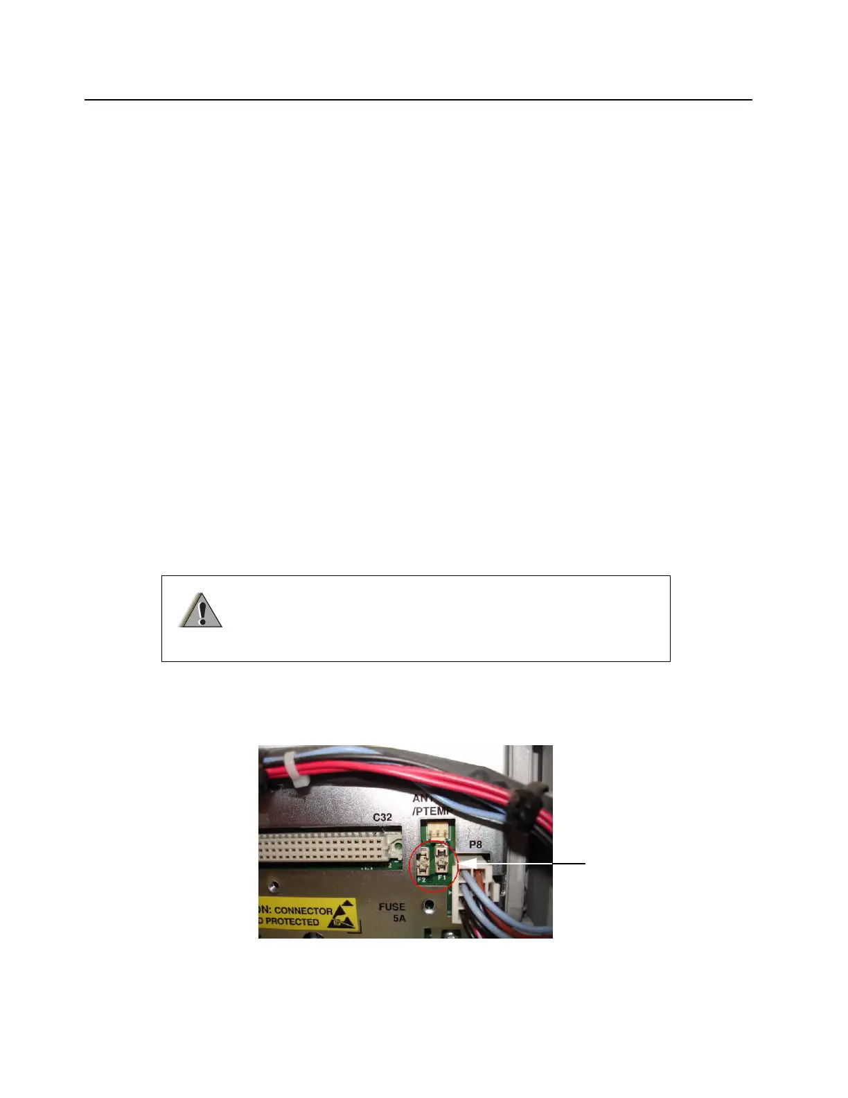
For procedure to check the fuses for the two 14.2 VDC (F1 and F2), refer to Figure 6-3.
Figure 6-3 Rear view with fuse cover plate removed
To avoid electrical shock, turn off base station/repeater power at
source (e.g. AC breaker) before replacing any fuses.
W A R N I N G
Fuse F1 and Fuse F2
 Loading...


