13-14 MTR3000 Programming and Tuning: Modulation Limit Alignment
13.6 Modulation Limit Alignment
This feature is to set the modulation limit of the radio for MTR3000 and MTR2000 MOTOTRBO
Digital Upgrade.
13.6.1 Tuning Procedure (with no Tx Data and no PL)
1. Connect the radio’s antenna port to the attenuation pad, if necessary, before connecting to
the Communication Analyzer.
2. Power the base station/repeater from either an AC or DC source.
3. Apply a 1 kHz signal at 1.2 Vrms to Pin 1 of the J7 backplane connector.
- Signal ground is Pin 9 of the J7 backplane connector.
4. Launch the Tuner application and click the “Read” button to read the softpot values.
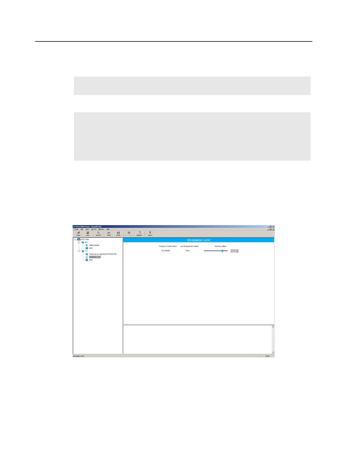
5. Select “Modulation Limit” under the Tx menu in the tree view (Refer to Figure 13-11).
Figure 13-11 Tx Menu tree (Tuning Procedure with no Tx data)
6. Enter the tuning frequency into the Communication Analyzer (the value displayed on the
Tuner GUI).
7. Click the “PTT Toggle” button within the Tuner environment to key up the radio.
Note
A modulation limit alignment is not needed if the radio is used in repeat mode. This is
always the case when the radio is in digital mode.
Note
1. Under the “Accessories” menu within the CPS, if the “Audio Type” is set to “Rx & Tx
Filtered Squelch” and the “Analog Accessory Emphasis” is set to “De & Pre”, then a
modulation limit alignment is not needed. In this configuration, the modulation limit is
always set to 92% RSD by the base station/repeater software.
2. If data or PL signaling is applied to Pin 13 of the J7 connector, proceed to Section 13.6.3
on page 13-16.
 Loading...


