MTR2000 MOTOTRBO Digital Upgrade: New Connections 10-5
7. Secure the Transceiver Assembly to the bottom plate by fastening the screws in Step 3
(Refer to Figure 10-3).
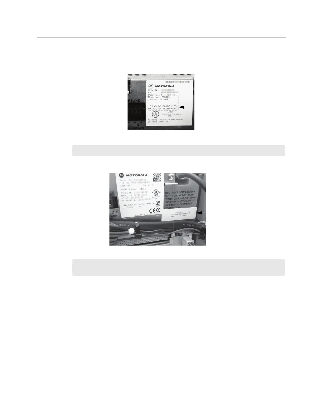
8. Affix the provided MTR3000 FCC upgrade label to the area noted in Figure 10-5.
Figure 10-5 Location to affix the MTR3000 FCC upgrade label
9. Affix the provided Part 68 label to the area noted in Figure 10-6 (if not already present).
Figure 10-6 Location to affix the Part 68 label
10. Reconnect the Exciter-to-PA Coaxial Cable and Rx Input Cable.
10.3 New Connections
After the base station/repeater equipment has been mechanically installed, connections must be
made. This involves making the following new connections to:
• J7 Backplane Connector to support the following analog third party boxes (If applicable)
- Community Repeater Panel
- Tone Remote Controller (Console Connection)
- LTR Trunking Controller
- Passport (NTS) Controller
- Phone Patch
- Deskset
Note
The label must not cover the serial number of the MTR2000 Base Station/Repeater.
Note
The Part 68 label is supplied if the MTR3000 Wireline Card is ordered as an option with the
MTR2000 MOTOTRBO Digital Upgrade Base Station/Repeater.
Designated area
Designated area
 Loading...


