MTR3000 Base Station/Repeater: Basic Troubleshooting 1-13
The station operator will then evaluate the problem locally or remotely, as the station will maintain an
Alarm Log with the name of the alarm that has failed since the last power up. Via the RDAC
application’s Alarm Log, the alarm messages will aid in identifying the FRU that failed along with the
fault condition.
After booting up the base station/repeater, the 6 LEDs (Power/Status, Tx Slot 1, Tx Slot 2, Rx Slot 1,
Rx Slot 2 and the Mode LEDs) will flash in unison.
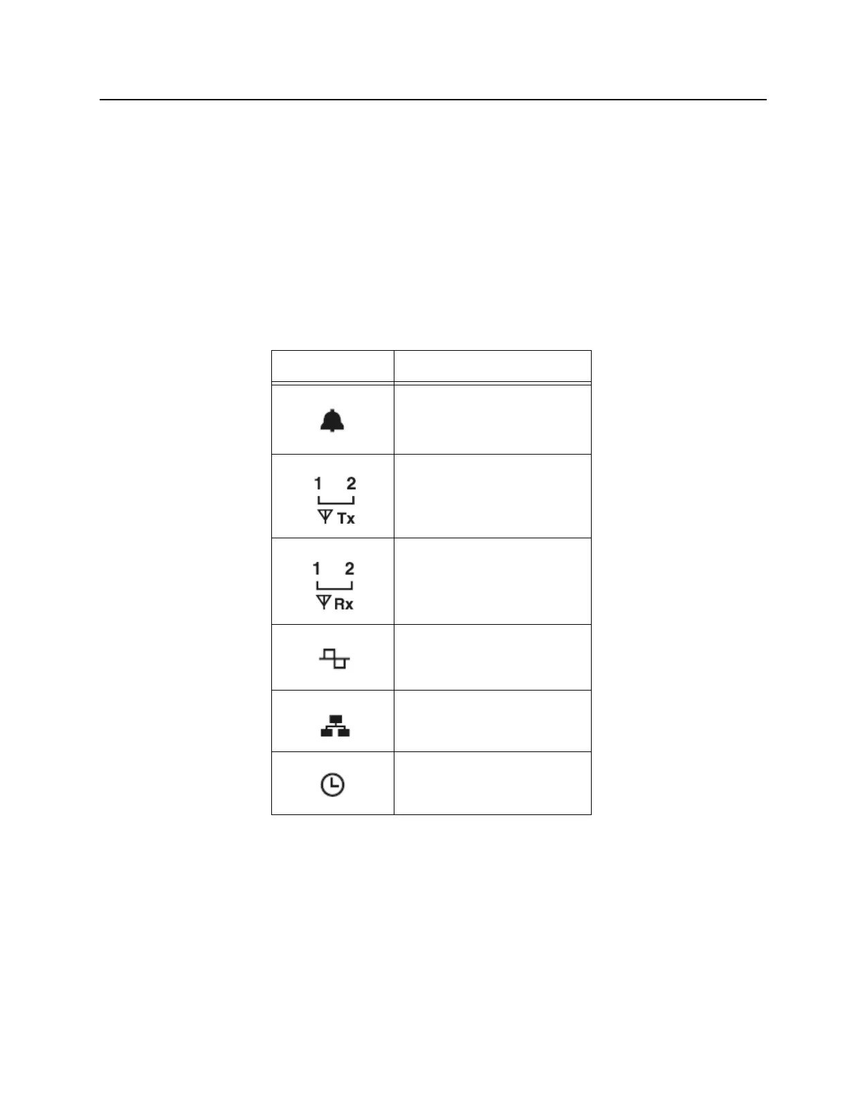
The general status and condition of the MTR3000 Base Station/Repeater can be obtained by
observing the eight LED indicators on the front panel. Table 1-8 shows the LED symbols and their
meaning, while Table 1-9 identifies the information conveyed via the LED indicators. Table 1-10
shows the alarm diagnosis table and probable diagnosis to aid in identifying the fault.
Table 1-8 Front Panel LED indicators
LED
Definition
Status
Tx Slot 1 (for label number 1)
Tx Slot 2 (for label number 2)
Rx Slot 1 (for label number 1)
Rx Slot 2 (for label number 2)
Mode
Ethernet Link
Reference
 Loading...


