9-32 MTR3000 Radio Frequency Distribution System (RFDS) Equipment: Field Tuning Procedures
Figure 9-24 UHF Duplexer Field Tuning Procedure (continued)
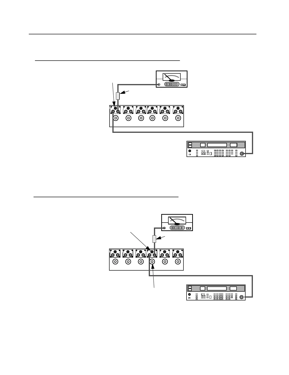
4. Tuning High Notch Loop Assemblies
1. Set up test equipment as shown,
connecting to cavity no.1.
2. Use screwdriver to adjust notch
adjustment screw for cavity no.1 to
obtain a minimum reading on the
millivoltmeter. (Reduce the range on
the millivoltmeter as necessary to
reach true minimum reading.)
3. Use open end wrench and tighten
lock nut carefully, making sure notch
adjustment screw does not shift
position.
4. Repeat steps 1–3 for cavities no.2
and no.3.
5. Tuning Low Notch Loop Assemblies
1. Set up test equipment as shown,
connecting to cavity no.4.
2. Use screwdriver to adjust notch
adjustment screw for cavity no.4 to
obtain a minimum reading on the
millivoltmeter. (Reduce the range on
the millivoltmeter as necessary to
reach true minimum reading.)
3. Use open end wrench and tighten
lock nut carefully, making sure notch
adjustment screw does not shift
position.
4. Repeat steps 1–3 for cavities no.5
and no.6.
5. Reconnect the cables on the
duplexer. Make sure that the cables
are returned to their original position
on the Duplexer.
Boonton 92E RF
Millivoltmeter
Range set to +10 dBm
Frequency set to Rx or Tx frequency,
whichever is HIGHER.
Output Level set to +10 dBm.
Notch Adjustment
Screw and Lock
Nut
6 dB In-line
pad (50
Ω)
1 2 3 4 5 6
HP8656B Signal Generator
Notch Adjustment
Screw and Lock Nut
6 dB In-line pad
(50 Ω)
Boonton 92E RF
Millivoltmeter
Range set to +10 dBm
Frequency set to Rx or Tx frequency,
whichever is LOWER.
Output Level set to +10 dBm.
Resonator Pass Adjustment
Screw and Lock Nut
1 2 3 4 5 6
HP8656B Signal Generator
 Loading...


