MTR3000 Performance Check or Testing: Verifying Receiver Circuitry 12-7
HELP
TAB
1
SELECT
CANCEL
IFR 390I Digital Radio Test Set
TEST
HOLD
CONFIG
UTILS ENTER
MIC / ACC GEN T/RANT
RETURN
TEST PORT CH1 SCOPE CH2 1 2AUDIO INFCTN GEN / DEMOD OUT
0
.
#
ASSIGN
–
*
2
456
7
HELP
89
3
RF In / Out
Aeroflex 3900 Series
Communications
System Analyzer
To R e ce i v e
Antenna
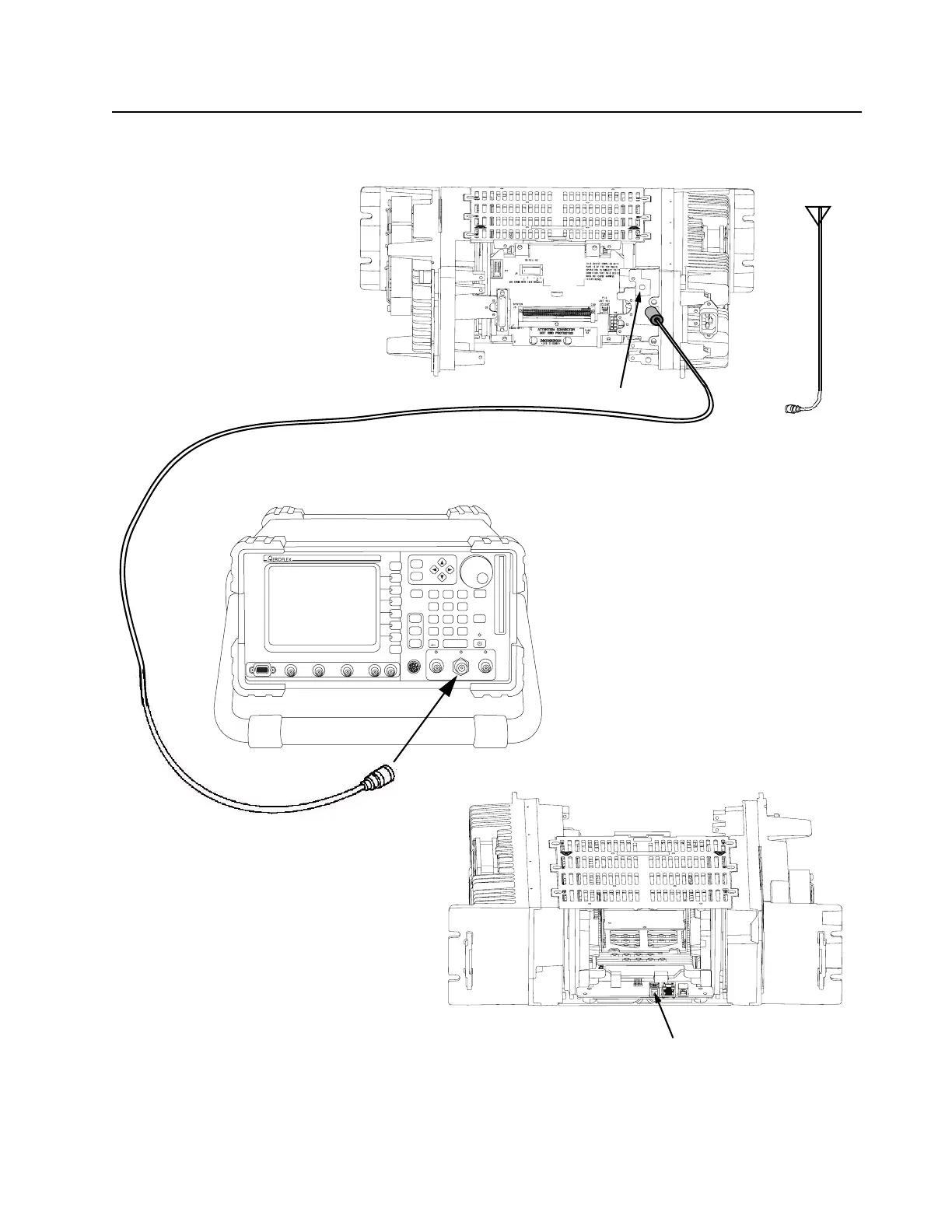
Figure 12-2 Test Equipment Setup for Verifying Receiver Circuit
1. Disconnect antenna cable
from N-type connector on
the base station/repeater.
3. Connect service speaker
to speaker connector on
Station Control Module.
Station – rear
Station – front
External Speaker Connector on SCM
2. Connect an N-to-N type cable between the base station/
repeater receive input and RF In / Out connector on
Aeroflex 3900 Series Communications System Analyzer.
Station Receive Input
 Loading...


