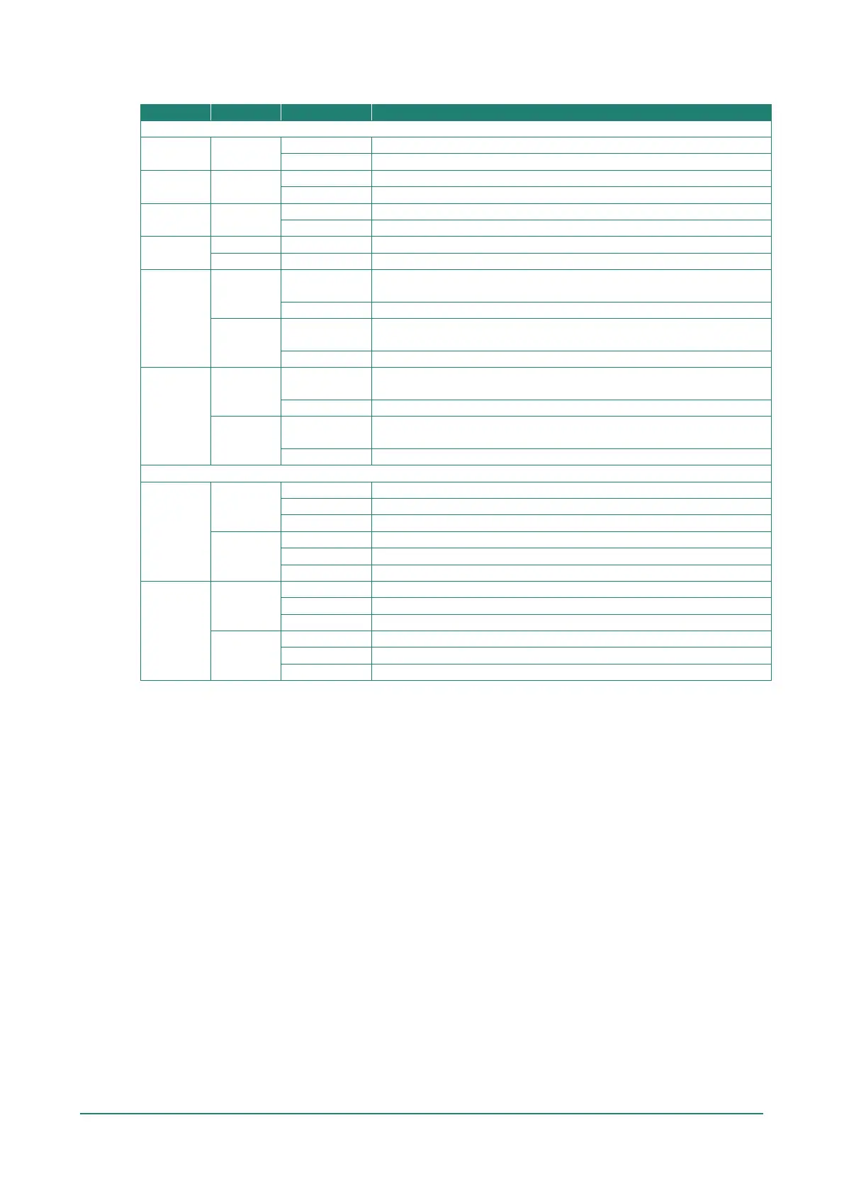
The following table summarizes how to read the device’s wireless settings from the LED displays.
Front Panel LED Indicators (System)
PWR1 Green
Power is being supplied from power input 1.
Power is not being supplied from power input 1.
PWR2 Green
Power is being supplied from power input 2.
Power is not being supplied from power input 2.
PoE Amber
Power is being supplied via PoE.
Power is not being supplied via PoE.
SYS
System initialization failure, configuration error, or system error.
System startup completed and is operating normally.
2.4GHz
Green
On
Client/Client-Router/Slave has established a Wi-Fi connection to an
AP/Master with a SNR value of 35 or higher.
Data is being transmitted over the 2.4 GHz band.
Amber
On
Client/Client-Router/Slave has established a Wi-Fi connection to an
AP/Master with a SNR value of less than 35.
Data is being transmitted over the 2.4 GHz band.
5GHz
Green
On
Client/Client-Router/Slave established a Wi-Fi connection to an
AP/Master with a SNR value of 35 or higher.
Data is being transmitted over the 5 GHz band.
Amber
On
Client/Client-Router/Slave has established a Wi-Fi connection to an
AP/Master with a SNR value of less than 35.
Data is being transmitted over the 5 GHz band.
LAN LED Indicators (RJ45 Port)
LAN 1
Green
Link established on the LAN port at 1000 Mbps.
Data is being transmitted at 1000 Mbps.
The LAN port’s 1000 Mbps link is inactive.
Amber
Link established on the LAN port at 10/100 Mbps.
Data is being transmitted at 10/100 Mbps.
The LAN port’s 10/100 Mbps link is inactive.
LAN 2
Green
Link established on the LAN port at 1000 Mbps.
Data is being transmitted at 1000 Mbps.
LAN port’s 1000 Mbps link is inactive.
Amber
Link established on the LAN port at 10/100 Mbps.
Data is being transmitted at 10/100 Mbps.
The LAN port’s 10/100 Mbps link is inactive.