ioLogik E1200 Series Initial Setup
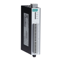
STEP 2. Use screws to fix the unit to the wall, as shown in the
diagram.
Reserve at least 1.5 cm of space above and below
that the installation can be done correctly.
At this point, if the mounting was done correctly, the unit should be
fixed to the wall.
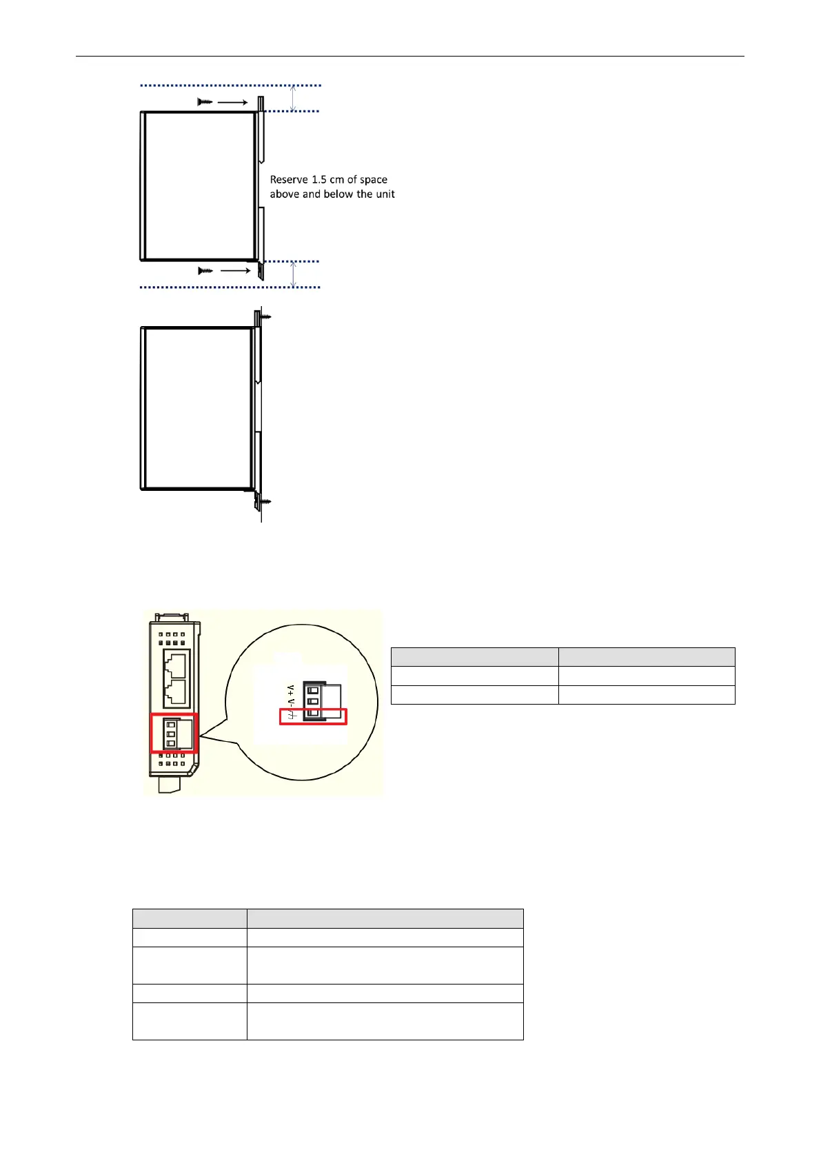
Grounding the Unit
Top View
has a grounding point located on the top
of
the terminal block. Connect the ground pin ( ) to earth
ground.
Item Suggested Setting
Wire range 12 to 24 AWG
Screw Torque 7 lb-inch
I/O Channel Jumper Setting
The following table shows jumper setting for each model of the ioLogik E1200 Series. We provide a more
detailed description of three different jumper settings.
Model Jumper Setting
E1212 DIO direction (DI, DO)
E1213 1. DIO direction (DI, DO)
2. EXT Power Configuration
E1240 AI mode (Voltage, Current)
E1242 1. DIO direction (DI, DO)
2. AI mode (Voltage, Current)