MiiNePort E2/E3 Introduction
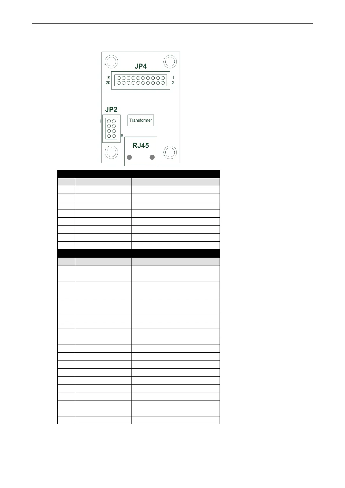
MiiNePort E3 Module Pin Assignment
Ethernet Pins (JP2)
Pin Signal Name Function
1 Reserve N/A
3 Reserve N/A
4 Reserve N/A
5 PoE signal pair 1 PoE power from Tx signal
6 PoE spare pair 1 PoE power from RJ45 4, 5 pin
7 PoE signal pair 2 PoE power from Rx signal
8 PoE spare pair 2 PoE power from RJ45 7, 8 pin
Serial Pins and Power Pins (JP4)
Pin Signal Name Function
1 Serial Rx Receive Serial Data
3 Serial Tx Transmit Serial Data
4 GPIO Programmable I/O
5 DCD Receive Line Signal Detector
6 GPIO Programmable I/O
7 RS485_EN0 RS-485 Enabled
8 GPIO Programmable I/O
9 RTS Request to Send
10 GPIO Programmable I/O
11 DTR Data Terminal Ready
12 Reserve N/A
13 DSR Data Set Ready
14 Reserve N/A
15 CTS Clear to Send
16 SW_Reset Reset to Factory Default
17 Reserve N/A
18 Reserve N/A
19 GND Circuit Ground
20 VCC Power Supply