MULTIPLEX
1. C
ONTENTS
1. Contents 16
2. Quick-Start 16
3. Introduction 17
3.1 The SMART SX philosophy 17
3.2 Features of the SMART SX 17
4. Safety notes, other information 18
5. Set contents / Accessories 20
6. Specification 20
6.1 SMART SX transmitter 20
6.2 RX-5 light M-LINK receiver 21
7. Handling 21
7.1 Transmitter controls 21
7.2 Receiver controls 21
7.3 Transmitter aerial 21
7.4 Inserting dry / rechargeable cells 22
7.5 Voltage monitor / operating times 22
7.6 Binding 22
7.7 Channel assignment 22
7.8 Mode switching 23
7.9 Servo reverse 23
7.10 Unlocking, activating and disabling
the throttle function 23
7.11 Trims 24
7.12 Dual Rates 24
7.13 Fail-Safe 24
7.14 Auxiliary (AUX) channel 24
7.15 Range checking 24
7.16 Model memory (ID) 24
7.17 Installing the receiver in the model 26
7.18 The SMART SX as Pupil transmitter 26
7.19 Firmware update / settings for
future RR+ models 26
7.20 Installing aluminium sticks 26
7.21 Speech output of telemetry data 27
8. Advice and Service
27
9. Care and Maintenance 27
10. CE Conformity Declarations
27
11. FFC Warning Statements 27
12. IC Warning Statements 27
13. Guarantee / Liability Exclusion 27
14. Disposal
28
15. Fault-finding 28
Congratulations on purchasing your new radio control
system. We are delighted that you have selected the
MULTIPLEX SMART SX M-LINK. You are now the
owner of a superb system for the newcomer to the
hobby of radio-controlled modelling. We hope you
have many hours of fun and success with your new
equipment.
2. Q
UICK
-S
TART
1. Unpack the transmitter and receiver
Store the documents safely.
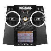
2. Insert the batteries
It is essential to maintain cor-
rect polarity (see adjacent illus-
tration). Reversed polarity may
ruin the transmitter and / or the
cells.
3. Binding
• Preparing the model
When binding is complete, the receiving system
immediately starts operating. Secure the model
carefully so that no damage can result if the propel-
ler should start turning.
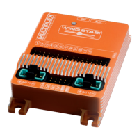
• Prepare the transmitter
Hold the multi-function
button pressed in and
switch the transmitter on,
then release the button
again. The LED flashes
at a high rate.
• Prepare the receiver
Switch the receiver on
with the SET button held
pressed in; the receiver
LED now flashes at a
high rate.
If binding is successful, both LEDs revert to a slow
flashing rate.
4. Check the directions of servo rotation
• Model with ID receiver
The transmitter emits an audible signal when it de-
tects the receiver. No further adjustments are re-
quired.
• Model with normal M-Link receiver (light or teleme-
try)
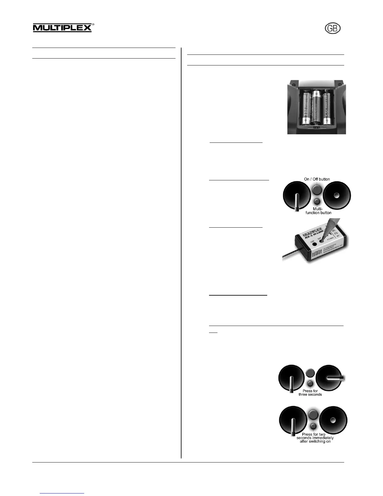
All the control surfaces (servos) must respond to
the sticks in the correct direction; check and re-
verse the servos if necessary: move the correct
stick to one end-point and hold the multi-function
button pressed in for
three seconds: the ser-
vo now reverses, and
moves to the opposite
end-point.
5. Carry out a range check
It is important to check radio
range before the first flight:
hold the multi-function but-
ton pressed in for two sec-
onds immediately after
switching on, and the LED
glows constantly. The transmitter now generates great-
ly reduced power, and emits an audible warning signal.