MULTIPLEX
radiation pattern which is ideal for the user, and com-
pletely new in the sphere of RC system transmitters:
all the radiated power is effectively concentrated in
the flight sector.
The 2.4 GHz
aerial integrated
into the trans-
mitter case is
always oriented
in the ideal
direction, dou-
bling the signal
density over the
radio link to the
model. In conjunction with the optimised transmitting
direction this aerial system provides a significant im-
provement in transmission security: effective range is
far beyond the limits of vision.
7.4 Inserting dry / rechargeable cells
The SMART SX transmitter is powered by three AA-
size dry cells; one set of cells is included in the set.
Open the battery compartment on the back of the
transmitter, and insert the dry cells as shown in the
illustration on page 7. Close the battery compartment
again. Remove the cells from the transmitter if you
know you will not use it for a long period, e.g. during
the Winter break.
Note:
It is essential to fit the batteries with correct polarity.
The negative terminal of each cell must mate with the
spring contact. Reversed polarity may ruin the trans-
mitter and / or the cells.
It is also possible to use three rechargeable cells in-
stead of the dry cells. However, these cells must al-
ways be recharged outside the transmitter, as no
charge socket is present. Be sure to use a suitable
battery charger.
7.5 Voltage monitor / operating times
The SMART SX transmitter features a permanent
warning function which alerts the user to low battery
voltage. When the dry or rechargeable cells are al-
most flat, you will hear an audible warning, and the
LED will flash red instead of yellow. If this should
happen, land the model or cease operations without
delay, and fit new or fully charged cells.
Thanks to the low energy requirement typical of 2.4
GHz equipment, the transmitter operates for the long
period of up to 25 hours with three AA dry cells.
7.6 Binding
The first time you make the connection between transmitter
and receiver the two components must be ‘bound’. For
safety’s sake remove the propeller before doing this. When
binding is complete, the receiving system immediately
starts operating. First secure the model carefully so that no
damage can result if the propeller should start turning. If
you are unsure, for safety’s sake remove the propeller first.
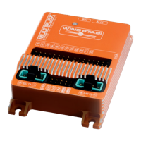
• Prepare the transmitter for binding
Switch the transmitter on
with the multi-function but-
ton pressed in, and then re-
lease the button again. The
Status LED flashes yellow
at a high rate.
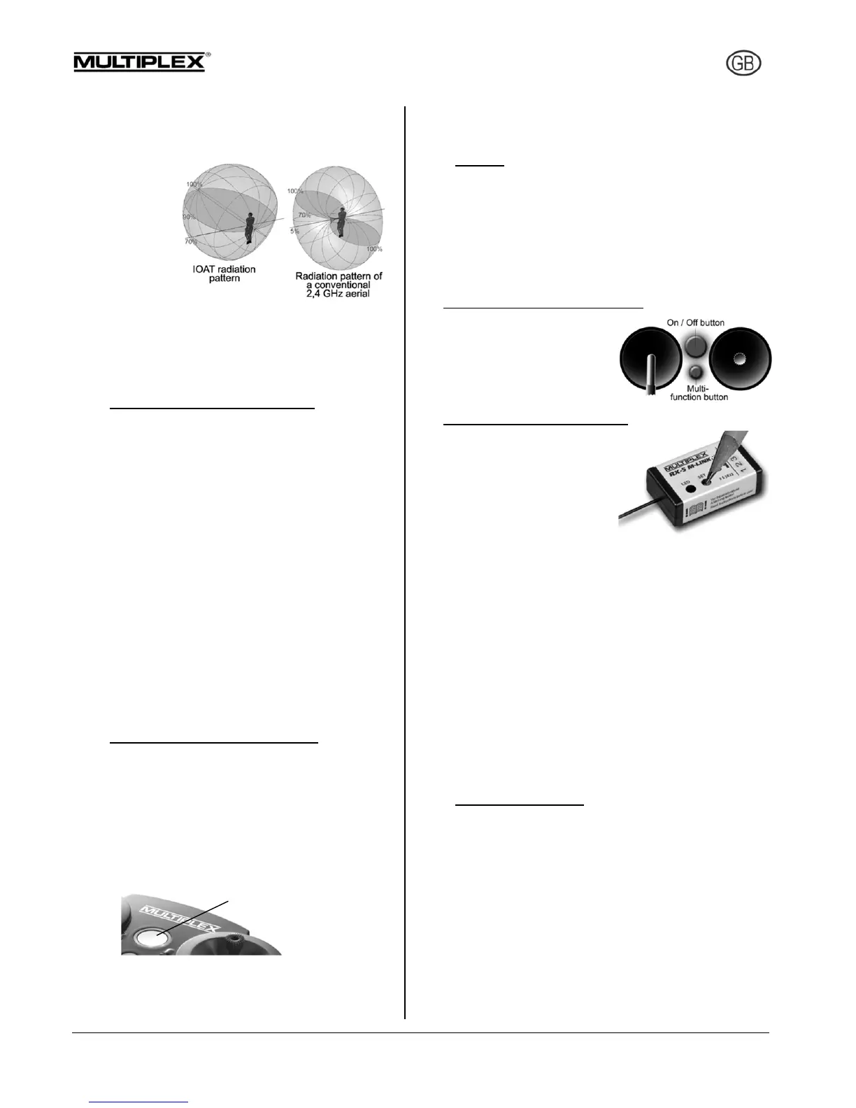
• Prepare the receiver for binding
Switch the receiver on with
the SET button pressed in.
The LED on the receiver
now also flashes yellow at a
high rate.
Place the transmitter and re-
ceiver close to each other.
Transmitter power is greatly reduced for the binding pro-
cess; the distance between the two units may need to be
20 cm or less. As soon as the transmitter and receiver have
“found” each other, the flashing rhythm on both compo-
nents changes to a slow rate. Any servos connected to the
receiver will now follow the movement of the corresponding
sticks.
The binding information is stored permanently in the re-
ceiver, i.e. the binding procedure only needs to be carried
out once.
If you are using an ID receiver, you will hear an audible
signal when binding is complete, and the transmitter auto-
matically loads the appropriate settings. This means that
you do not need to adjust settings 7.7 to 7.11 every time.
7.7 Channel assignment
The channel assignment of the SMART SX transmitter is
fixed; the sequence is as follows:
Channel 1: Aileron 1
Channel 2: Elevator
Channel 3: Rudder
Channel 4: Throttle
Channel 5: Aileron 2
Channel 6: AUX auxiliary function (min. six-channel
receiver required)
LED (Corona) flashes red