8-5
8.2.1
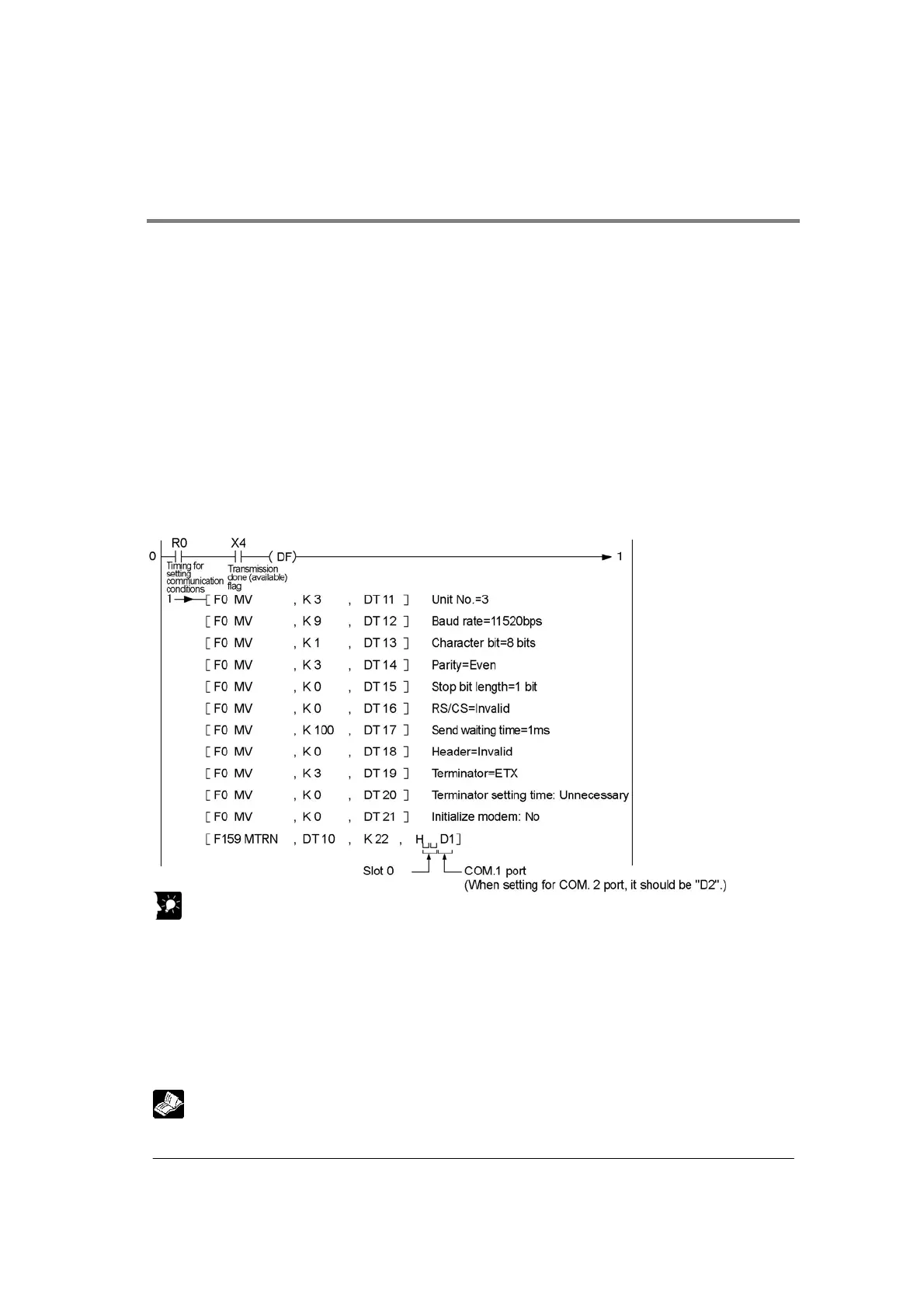
Example of Communicatio n Condition Setting using F159 (MTRN) Instruction
When the following conditions are specified for the COM. 1 port in the slot 0.
Unit No. : K3 : 3
Baud rate : K9 : 115200 bps
Character bit : K1 : 8 bits
Parity : K3 : Even
Stop bit length : K0 : 1 bit
RS/CS : K0 : Invalid
Send wWaiting : K100 : 1 ms
Header STX : K0 : not exist
Terminator : K3 : ETX
Terminator setting time : K0 : Unnecessary
Initialize modem : K0 : No
Explanation of program operation
If R0 is turned on when MCU is in the waiting status for transmission, the above communication
conditions are specified for the COM. 1 port in the slot 0.
Key Point:
• Specify “22 bytes” for the number of bytes of setting data when specifing the communication
conditions.
• All communicaiton conditions for registers should be specified all at once in advance in order to set the
communication conditions.
• The head of register (DT10 in the example) specified using F159 (MTRN) instruction is used by the
system. Valid data should be specified from the next address (DT11 in the example).
• Use the default settings for the conditions which is not needed to be set.
• Specify the settings for COM. 1 port and COM. 2 port separately.
• Some conditions cannot be changed depending on operating modes.
Reference: <Column of “Settable operation mode” in 8.2 Setting Communication Conditions and
Monitoring>