5-13
5.4 Connection Examp le of PLC Link
5.4.1
When using three PLCs
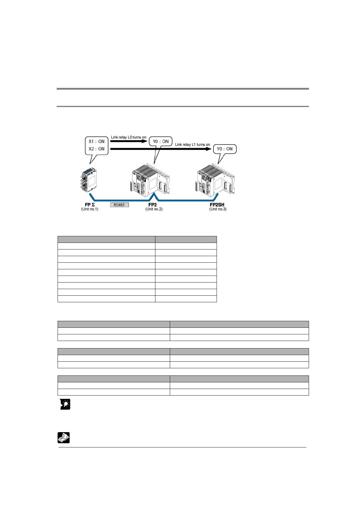
The following example demonstrates how the PLC can be connected to two other FPΣ PLCs using a
PLC link connection. In the example shown here, link relays are use. When X1 of control unit no. 1 turns
on, Y0 of unit no. 2 turns on. When X2 of unit no. 1 turns on, Y0 of unit no. 3 turns on.
System register settings
When using a PC(PLC) link, the settings are fixed as below. (The settings using the memory
switch are ignored.)
Setting Setting value
Baud rate 115200 bps
Character bit 8 bits
Parity Odd
Stop bit 1 bit
RS/CS (Only when using RS232C) Invalid
Send waiting time 0.00 ms
Header STX not exist
Terminator CR
Initialize modem No
Unit no. and communication mode settings
- Setting for FPΣ
ΣΣ
Σ of unit no. 1
Name Set value
COM port 1 unit no. 1 (setting using the unit no. setting switch)
COM port 1 communication mode PC(PLC) link (system register No. 412)
- Setting for FP2 of unit no. 2
Name Set value
COM port 1 unit no. 2 (setting using the unit no. setting switch)
COM port 1 communication mode PC(PLC) link (using the mode speed setting switch)
- Setting for FP2SH of unit no. 3
Name Set value
COM port 1 unit no. 3 (setting using the unit no. setting switch)
COM port 1 communication mode PC(PLC) link (using the mode speed setting switch)
Key Point:
Make sure the same unit number is not used for more than one of the PLCs connected through the
PC(PLC) link function.
The method of some settings for FP2/FP2SH is different from the method for FPΣ.
Reference: For the details on PC(PLC) link of FPΣ, refer to <FPΣ User’s Manual ARCT1F333>.