8-6
8.2.2
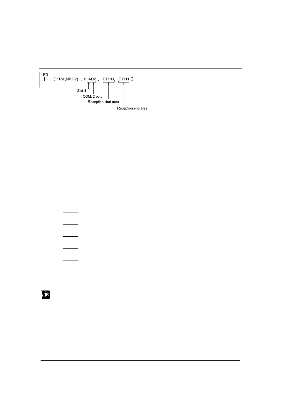
Example of Monitoring Co mmunication Condition using F161 (MRCV) Instruction
When R0 turns on, the communication condition of COM. 2 port will be stored in the next address
(DT101) of the receive buffer starting with DT100 to DT111.
An example of data read after the above program was executed is shown below.
DT100 K22
ĸNumber of bytes K22 (11 words) of the received communication condition data is
stored.
DT101 K3
ĸUnit No.: 3
DT102 K7 ĸBaud rate: 38400 bps
DT103 K1 ĸCharacter bit: 8 bits
DT104 K2 ĸParity: Odd
DT105 K0 ĸStop bit length: 1 bit
DT106 K1 ĸRS/CS control: Valid
DT107 K0 ĸSend waiting time: Immediate
DT108 K0 ĸHeader STX: STX not exist
DT109 K0 ĸTerminator: cR
DT110 K0
ĸTerminator judgement time: Invalid(Valid only when the end code is set to K2:
Time.)
DT111 K0 ĸInitialize modem: No
Key Point:
• 12 words should be assured for the receive buffer.
• COM. 1 port and COM. 2 port should be read separately.