2-4
2.2 FP2 Communicati on Blocks
2.2.1
Types of Communication Blocks
There are three types of communication cassettes, each having a particular field of application.
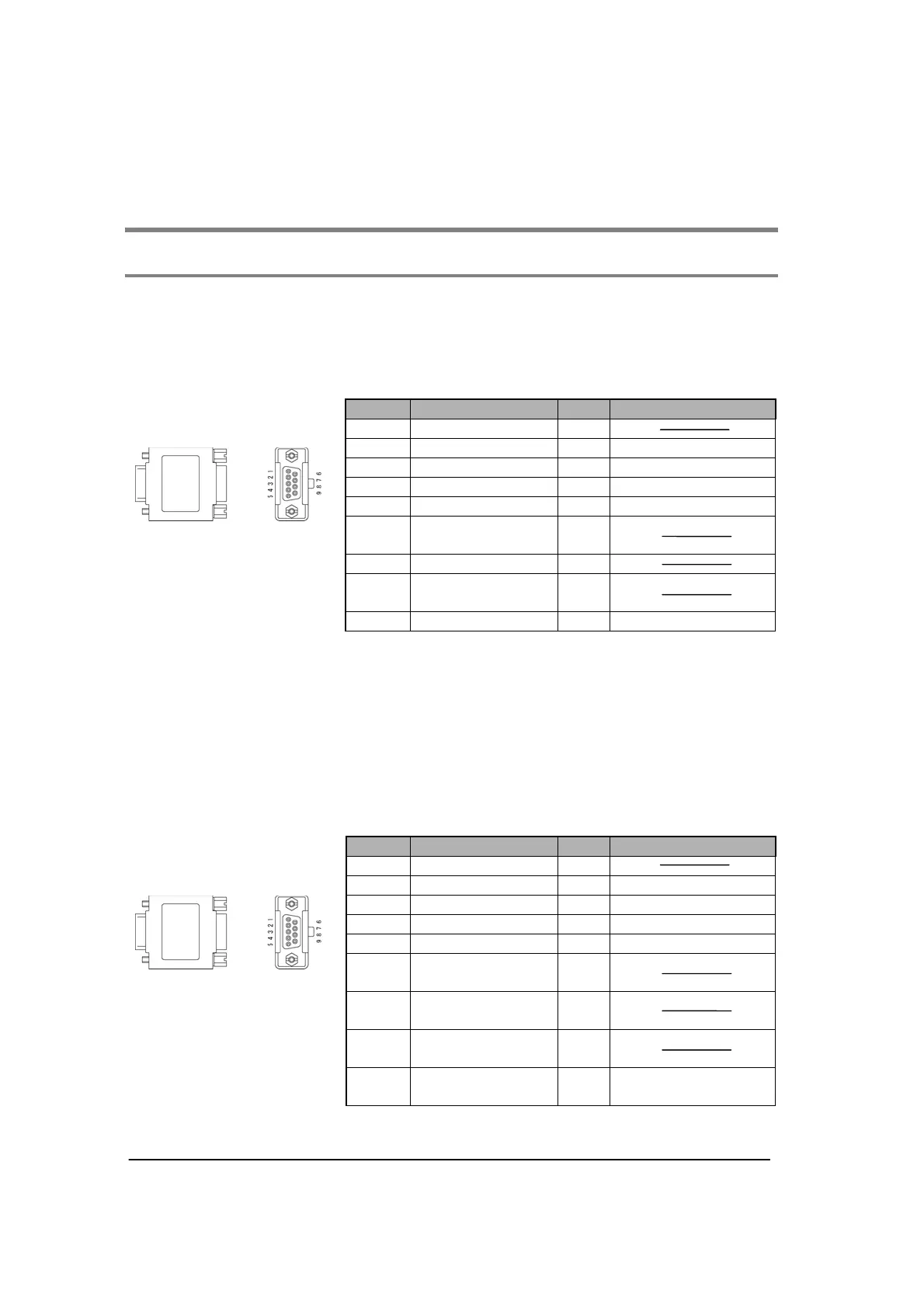
FP2 communication block (RS232C) FP2-CB232 (AFP2803)
This communication block is a 1-channel unit with a five-wire RS232C port. It supports 1:1 computer
links, general-purpose serial communication and PC(PLC) link between two units. RS/CS control is
possible in general-purpose serial communication mode.
Pin No. Name Abbr. Signal direction
1 (Not connected) (NC)
2 Send Data SD Unit to external devices
3 Receive Data RD External devices to Unit
4 Request to Send RS Unit to external devices
5 Clear to Send CS External devices to Unit
6
(Connection
unavailable)
-
7 Signal Ground SG
8
(Connection
unavailable)
-
9 Data terminal ready ER Unit to external devices
Note1) RS (Request to Send) is controlled at Y contact.
Note2) When setting the RS/CS control to “Able”, data cannot be sent without the pin CS (Clear to Send).
When using with a three-wire port, short-circuit the pin RS and CS, or disable them.
Note3) The ER signal is shorted in the RS signal and the communication block.
Note4) Do not connect to the pin “connection unavailable”.
Note5) The shell part and the mounting screw part of the connector is connected to the ground terminals
of the power supply unit.
FP2 communication block (RS422) FP2-CB422 (AFP2804)
This communication block is a 1-channel unit with a four-wire RS422 port. It supports 1:1 computer link,
general-purpose communication and PC(PLC) link (MEWNET-W0) between two units.
Pin No. Name Abbr. Signal direction
1 (Not connected) (NC)
2 Send Data SD+ Unit to external devices
3 Receive Data RD+ External devices to Unit
4 Send Data SD- Unit to external devices
5 Receive Data RD- External devices to Unit
6
(Connection
unavailable)
-
7
(Connection
unavailable)
-
8
(Connection
unavailable)
-
9
(Connection
unavailable)
- Unit to external devices
Note) The shell part and the mounting screw part of the connector is connected to the ground terminals
of the power supply unit.