2-3
Installation position for communication block
The communication blocks are installed in COM.1 and COM.2.
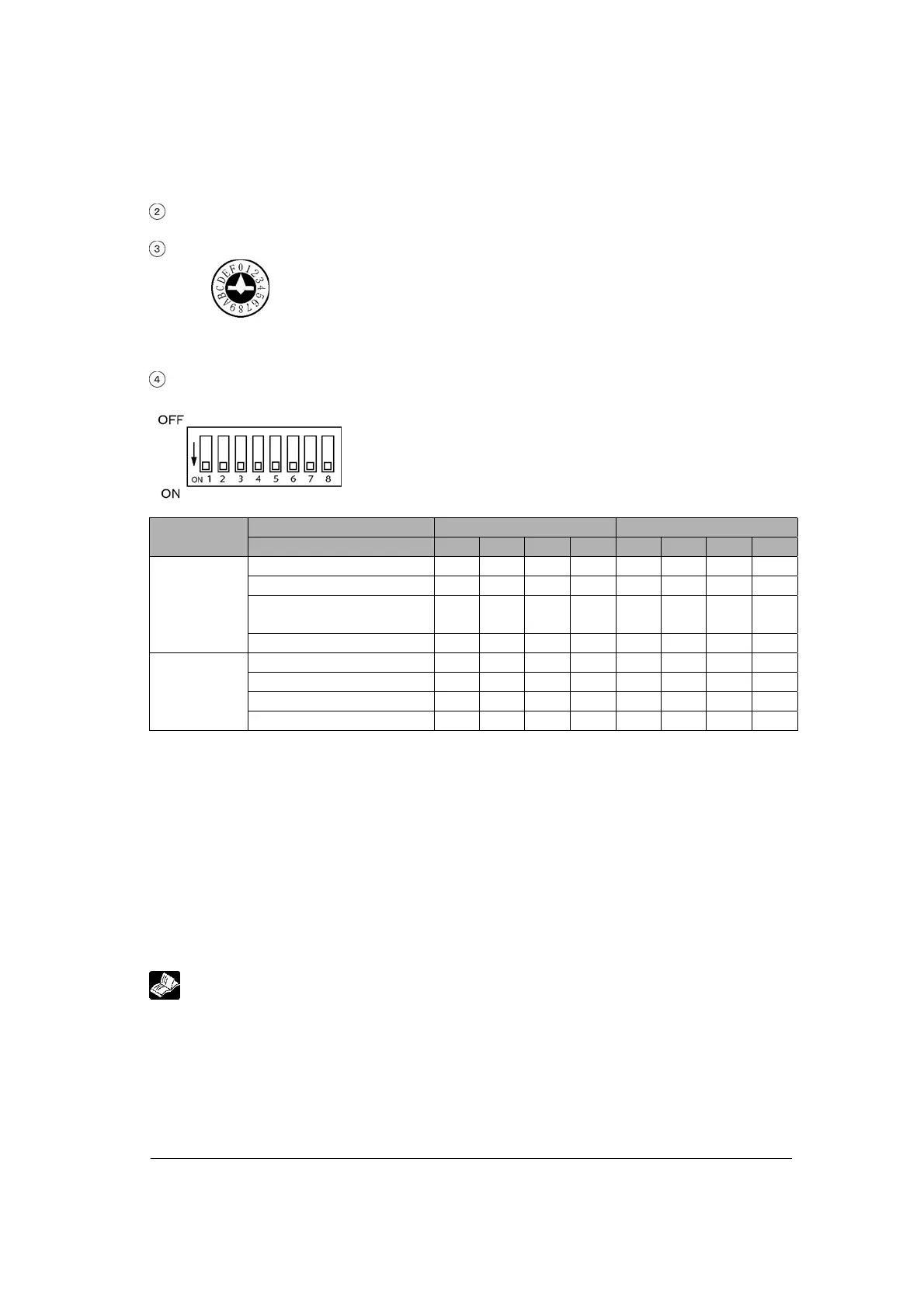
Unit No. setting switch
Unit No. for the COM.1 is set when the PC(PLC) link and computer link is
selected for the operation mode.
Unit No. can be selected in a range of 1 to 15.
• Factory default setting: 0 (memory switch selection)
Mode speed setting switch
Used to set the operation mode and communication speed.
Port COM. 1 COM. 2
Switch No. 1 2 3 4 5 6 7 8
Spare OFF OFF OFF OFF
PC(PLC) link ON OFF ON OFF
General-purpose serial
communication
OFF ON OFF ON
Operation
mode
Computer link ON ON ON ON
115200 bps OFF OFF OFF OFF
19200 bps ON OFF ON OFF
9600 bps OFF ON OFF ON
Baud rate
Memory switch ON ON ON ON
Note) If selecting the setting marked with diagonal lines, the setting error occurs.
• Factory default setting
Operation mode: Computer link
Communication unit No.: 1 (Memory switch and computer link are selected.)
Baud rate: 9600 (Memory switch selection)
Character bit: 8
Parity: Odd
Stop bit length: 1
RS/CS: Disable
Note) The factory default settings for the mode speed setting switch (dip SW) are all ON.
Reference:
For the detail on the communication settings (unit No., memory switch setting, etc.), refer to
<4.3.3 Unit No. Settings> and <4.3.3 Memory Switch>