6-8
6.4 Communication w ith External Devices
6.4.1 Programming Example of General-purpose Serial Communication
The F159 (MTRN) and F161 (MRCV) instructions are used to send and receive data via the specified
COM port.
F150 (READ) nor F151 (WRT) instruction which is effective with the serial data unit (AFP2460) is not
available with MCU.
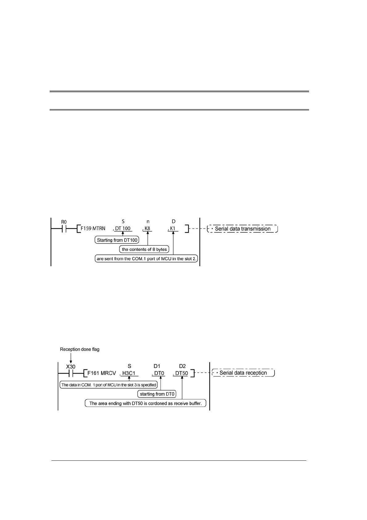
Transmission of data
The amount of data specified by “n” is sent to the external device from among the data stored in the data
table, starting with the area specified by “S”, through the COM port specified by “D”. Data can be sent
with the start code and end code automatically attached. A maximum of 2048 bytes can be sent. When
the program below is run, the eight bytes of data contained in DT101 to DT104 and stored in the send
buffer starting from DT100 are sent from COM port 1.
MCU starts the transmission within 10 µs normally (within a maximum of 500 µs approx. in the PC(PLC)
link mode) right after the execution of the instruction.
Reception of data
The data received in the communication port of MCU in the slot No. specified by “S” is read and stored in
the data table saved by the specifications from “D1” to “D2”.
A maximum of 2048 bytes can be received.
In the program below, when X30 (reception done flag) (including the terminator data) turns on, the
received data in the COM. 1 port of the MCU located in the slot 3 is stored from DT1 specified for the
receive buffer.
The number of received bytes is stored in DT0.