2-2
2.1 FP2 Multi Commu nication Unit
2.1.1
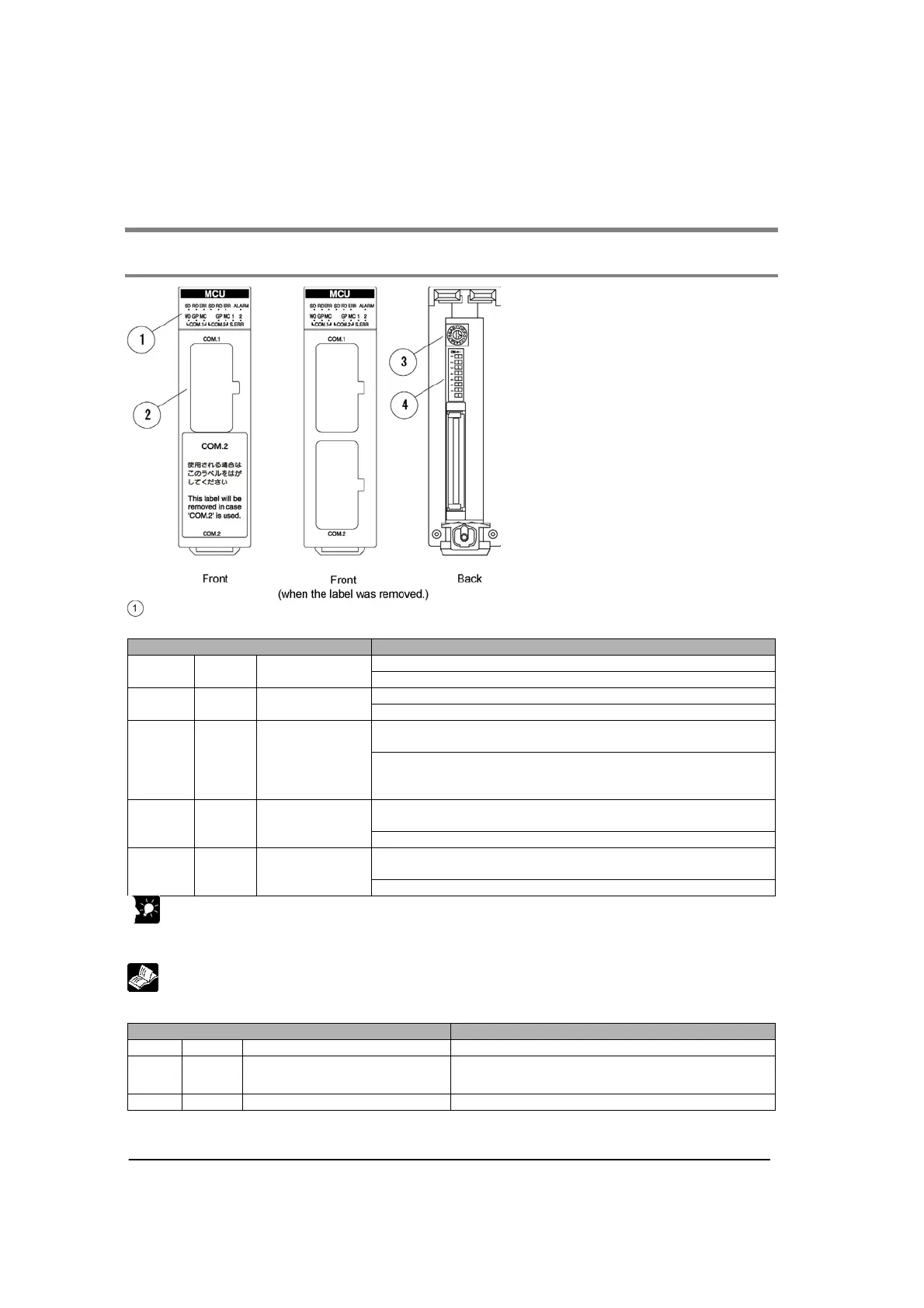
Parts and Functions
Operation indicator LEDs
Status indicator LED
Display Operation
Flashes while data is being sent.
SD Green
Send Data
monitor
Goes out when no data is being sent.
Flashes while data is being received.
RD Green
Receive Data
monitor
Goes out when no data is being received.
In PC(PLC) link mode: Lights if PC(PLC) link error occurs.
In other modes: Lights if communication error occurs.
ERR Red
Communication
error
In PC(PLC) link mode: Goes out if PC(PLC) link is liked up.
In other modes: Goes out if no communication error
occurs.
Lights if setting error occurs.
(The numbers at the top “1” and “2” mean COM. port No.)
S. ERR Red Setting error
Goes out in normal status.
Lights if unit error occurs. (Lights if watch dog timer error
occurs.)
ALARM Red Alarm
Goes out if no error occurs.
Key Point:
The communication error LED lights when the receive error occurs.
Receive error: Parity, framing, overrun, buffer capacity overflow, receive buffer FULL
Reference: <8.3 MCU Status Monitor>
Operation mode LED
Display Operation
W0 Green PC(PLC) link mode Lights in PC(PLC) link mode.
GP Green
General-purpose serial
communication mode
Lights in General-purpose serial communication
mode.
MC Green Computer link mode Lights in computer link mode.
Note) W0 (PC(PLC) link mode) is not available for COM. 2.