4-6
4.3 Settings
Specify modes, communication conditions and unit numbers.
4.3.1
Operation Mode Setting
Specify the mode for each COM. port.
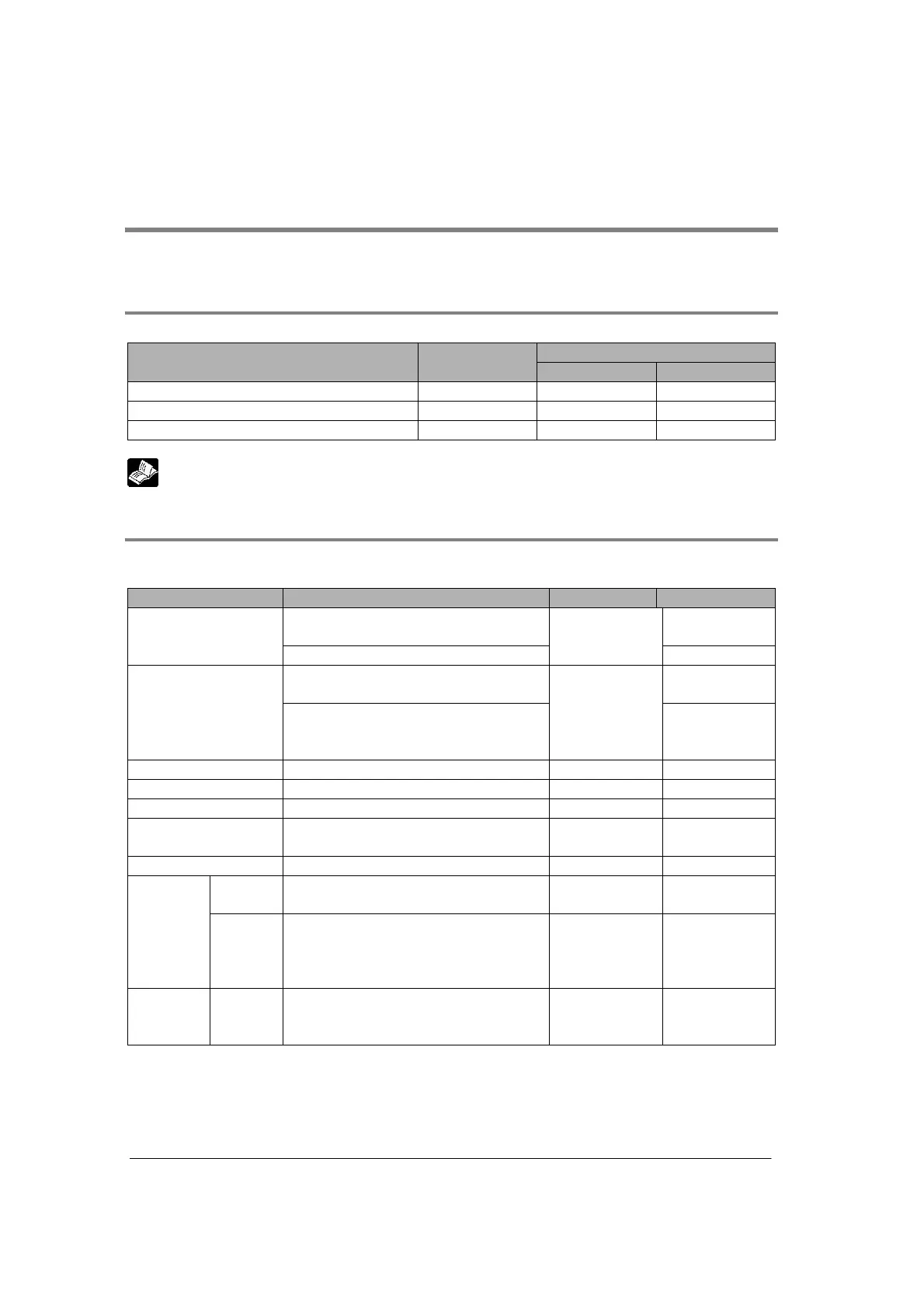
Memory switch
Mode setting
Mode speed
setting switch
MCU setting F159 (MTRN)
PC(PLC) link AN/AN/A
General-purpose serial communication AN/AA
Computer link AN/AA
(A: Available N/A: Not available)
Reference: <4.4.3 Memory Switch>
4.3.2
Communication Condition Setting
Specify the communication condition for each COM. port. The memory switch setting is made by the
MCU setting or F159 (MTRN) instruction.
Item Allowable setting value Initial value Setting
0 to 15 (can be set for COM.1 port only)
Unit No. setting
switch
Unit No.
1 to 99
1
Note5)
Memory switch
9600, 19200, 115200 bps
Mode speed
setting switch
Baud rate
300 to 230400 bps
Only available when selecting memory
switch
9600
Memory switch
Character bit 7 bits, 8 bits 8 Memory switch
Parity Odd, Even, Parity0, None Parity Odd Memory switch
Stop bit length 1 bit, 2 bits 1 Memory switch
RS/CS(only with
RS232C)
Note1)
Invalid/Valid Invalid Memory switch
Send Waiting time 0 to 100 ms (0.01 ms unit) 0 Memory switch
Header
STX
Not exist/Exist Not exist Memory switch
Only for
general-
purpose
serial
communi-
cation
Termi-
nator
Note2)
cR, cR+Lf, ETX
Timeout (0.01 to 100 ms)
In 0.01 unit
cR Memory switch
Others
Initialize
modem
Note3)
No/Yes No Memory switch
Note1) When setting the RS/CS to be invalid, the RS signals from MCU can be always received, and the
CS signals are always ignored.
Note2) If the terminator is set to “Timeout=0”, the data reception will complete when the time for more
than approx. 3 characters has passed from the time that last data was received.