2-12
2.4.2
Confirming the I/O Number Allocation
Like other units, the Multi Communication Unit (MCU) also allocates inputs (X) and outputs (Y). Each
MCU has 16 inputs and 16 outputs, for a total of 32 contacts.
The I/O numbers and slot numbers are always necessary when creating a program. These vary
depending on the position at which the unit is installed in the backplane. Always check to see if the
numbers match the design.
Confirming the I/O Number Allocations
The occupied I/O areas for all of the units mounted between the CPU unit and the MCU should be
confirmed. The next number is allocated as I/O areas for the MCU.
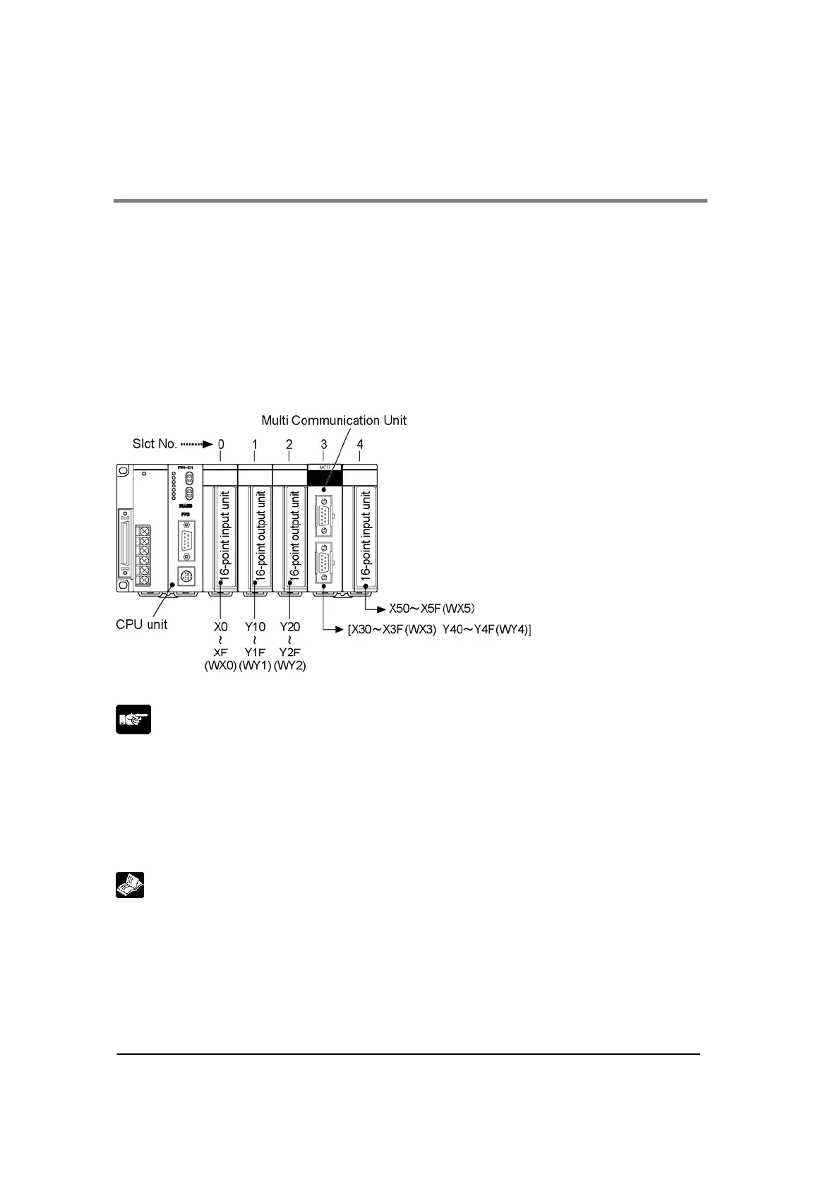
Example:
The following is an example of MCU being mounted in sueccession following three 16-point I/O units.
Note:
• Regardless of the mode settings for the COM. ports, the allocations of 16SX/16SY are necessary.
• If there are any empty slots between the CPU and the Multi Communicaiton Unit (MCU), check to see
whether an I/O area has been allocated to the empty slot.
• If I/O mount allocation and automatic allocation are being caarried out, 16 points for each type of
allocation will automatically be assigned to empty slots.
• If the CPU unit being used is a 2-module type, also check any I/O areas occupying the units
incorporated in the CPU unit.
Reference:
For information on how I/O allocations are made, refer to <FP2/FP2SH Hardware Manual>.