9-8
(0: OFF, 1: ON)
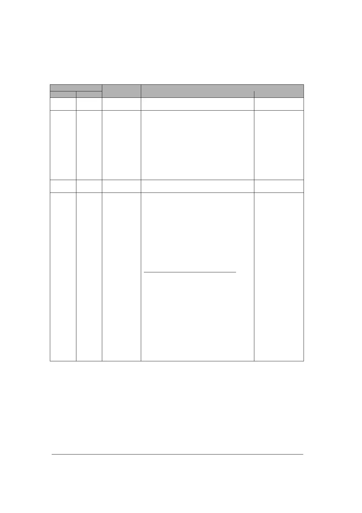
Output signal
COM. 1 COM. 2
Name Description
Effective
communication
Y10 to
Y17
Y10 to
Y17
Undefined Do not turn on “undefined”.
(Default setting is 0.)
None
Y18 Y19 RTS signal
output
The transmission from the devices
communicating with can be controlled by
turning this output on.
Permit the transmission from the devices
communicating=0
Prohibit the tranmission from the devices
communicating=1
The CTS singla sent from the devices
communicating can be monitored by X8 and
X9.
Effective only
when setting the
RS/CS to be valid
and using the
RS232C
communication
cassette.
Y1A to
Y1D
Y1A to
Y1D
Undefined Do not turn on “undefined”.
(Default setting is 0.)
None
Y1E Y1F Request to
reset CH
Communication channels can be reset by
turning on Y1E or Y1F.
No request to reset=0
Request to reset=1
After 1 is output and the completion of the
reset is confirmed by XE/XF, return to 0.
The reset is performed only once when this
signal rises.
Details on the channel reset operation
The following operations are performed.
1: Discontinues transmission
2: Discontinues reception
3: Clears receive buffer
4: Resets communication parameters
5: Clears error information
(However, only errors which can be
cleared)
This function can be used to delete
unnecessary received data or to clear
errors before starting normal reception.
General-purpose
serial
communication
Note) The operation to reset channels can be automatically performed by executing the following
processes as well as Y1E/Y1F.
1: When setting/changing communication parameters using MTRN instruction.
2: When changing operation modes (switching between the general-purpose communication and the
computer link) using MTRN instruction.
3: When turning the PLC power supply on, or when changint the mode from PROG. to RUN in case that
the MCU setting has been done using the tool.
However, the reset done signal of XE/YF does not turn on in the above case.