5-8
For PC(PLC) link 1
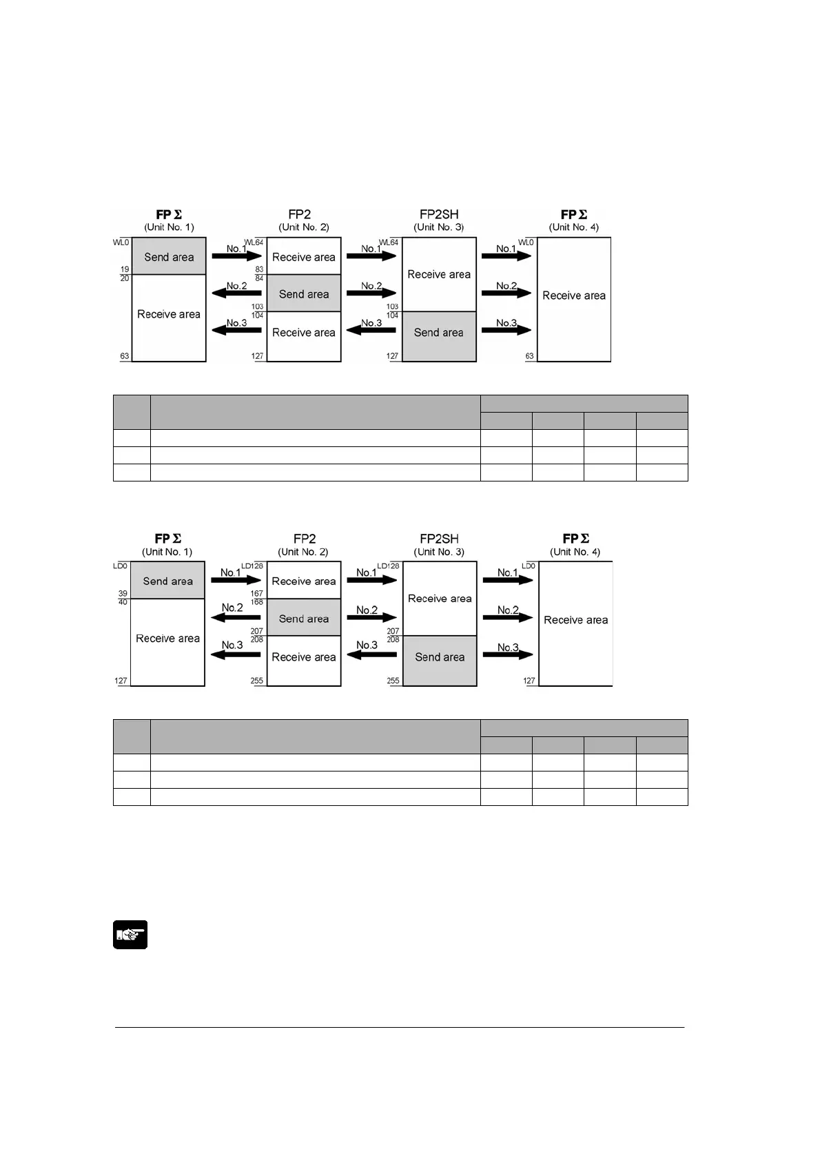
Link relay allocation
System registers
Setting for various units
No. Name
No. 1 No. 2 No. 3 No. 4
50 Range of link relays used 64 64 64 64
52 Starting No. of word for link relay 0 84 104 64
53 Link relay transmission size 20 20 24 0
Note) No. 50 (range of link relays used) must be set to the same range for all the units.
Link register allocation
System registers
Setting for various units
No. Name
No. 1 No. 2 No. 3 No. 4
51 Range of link registers used 128 128 128 128
54 Starting No. for link register transmission 0 168 208 0
55 Link register transmission size 40 40 48 0
Note) No. 41 (range of link registers used) must be set to the same range for all the units.
When link areas are allocated as shown above, the No. 1 send area can be sent to the No. 2, No. 3 and
No. 4 receive areas. Also, the No. 1 receive area can receive data from the No. 2 and No. 3 send areas.
No. 4 is allocated as a receive area only, and can receive data from No. 1, No. 2 and No. 3, but cannot
transmit it to other stations.
Note:
Therea is no area for PC(PLC) link 1 with FPΣ. Even when using the PC(PLC) link1 at MCU side, the link
relays and link registers No. to be used at FPΣ side are WL0 to WL63 and LD0 to LD127.
FP2: WL65 ⇔ WL1 : FPΣ
LD200 ⇔ LD136