W415-1794 / 06.28.18
EN
44
finishing
!
WARNING
52.1
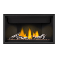
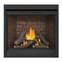
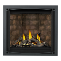
• Failure to position the logs in accordance with these diagrams or failure to use only logs specifi cally approved
with this appliance may result in property damage or personal injury.
• Logs must be placed in their exact location in the appliance. Do not modify the proper log positions, since
appliance may not function properly and delayed ignition may occur.
• The logs are fragile and should be handled with care.
INSERT PHAZER™ LOGS AND GLOWING EMBERS STATEMENT IF APPLICABLE:
52.1.1 FOR NAPOLEON
52.1.2 FOR CONTINENTAL
note:
Log numbers are located on the bottom or back of the logs.
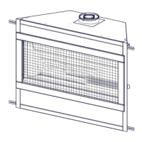
IF APPLICABLE, INSERT DRAWING OF BURNER/SUPPORT WITH APPROPRIATE LA-
BELS (I.E. STUDS, PILOT SHIELD, BURNER PORTS, ETC.).
IF NOT APPLICABLE, HIDE THIS SECTION AND USE BOXES BELOW.
DRAFT
Burner Overview
IF APPLICABLE, USE THIS BOX TO SHOW
“NATURAL GAS ONLY” LOG PLACEMENT.
PLACE TEXT BOX HERE.
NOTE: ENSURE NOMENCLATURE IS
CONSISTENT THROUGHOUT.
PLACE TEXT BOX HERE.
NOTE: ENSURE NOMENCLATURE IS
CONSISTENT THROUGHOUT.
PLACE TEXT BOX HERE.
NOTE: ENSURE NOMENCLATURE IS
CONSISTENT THROUGHOUT.
PLACE TEXT BOX HERE.
NOTE: ENSURE NOMENCLATURE IS
CONSISTENT THROUGHOUT.
PLACE TEXT BOX HERE.
NOTE: ENSURE NOMENCLATURE IS
CONSISTENT THROUGHOUT.
PLACE TEXT BOX HERE.
NOTE: ENSURE NOMENCLATURE IS
CONSISTENT THROUGHOUT.
PLACE TEXT BOX HERE.
NOTE: ENSURE NOMENCLATURE IS
CONSISTENT THROUGHOUT.
PLACE TEXT BOX HERE.
NOTE: ENSURE NOMENCLATURE IS
CONSISTENT THROUGHOUT.
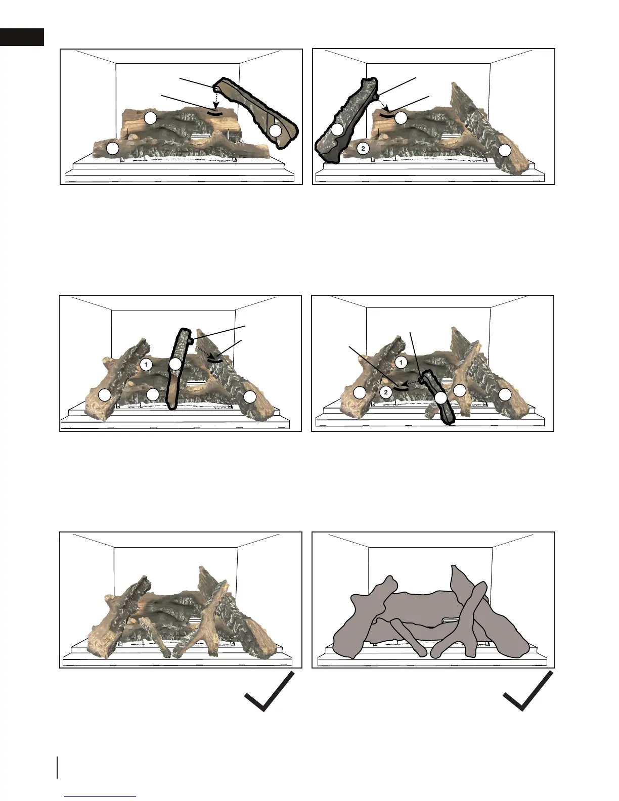
IF SPACE IS LEFT OVER, USE THIS BOX TO
SHOW CORRECT FINAL LOG
PLACEMENT WITH PHOTOS.
IF NOT, USE BOXES AS ABOVE.
IF SPACE IS LEFT OVER, USE THIS BOX TO
SHOW CORRECT FINAL LOG PLACEMENT
WITH LINE DRAWINGS.
IF NOT, USE BOXES AS ABOVE.
Propane Models Only:
Natural Gas Models Only:
PLACE TEXT BOX HERE.
NOTE: ENSURE NOMENCLATURE IS
CONSISTENT THROUGHOUT.
PLACE TEXT BOX HERE.
NOTE: ENSURE NOMENCLATURE IS
CONSISTENT THROUGHOUT.
IF APPLICABLE, USE THIS BOX TO SHOW
“PROPANE ONLY” LOG PLACEMENT.
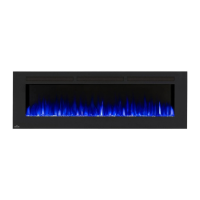
3. Place the bumpout on log #3 (W135-0762) into
the notch on the right side of log #1. Ensure
the other end rests on the lower part of the
media tray. Do not cover any burner ports.
4. Place the bumpout on log #4 (W135-0763) into
the notch on the left side of log #1. Ensure the
other end rests on the lower part of the media
tray. Do not cover any burner ports.
A2
A1
Stud
Pilot Shield
Air Cover
Stud
Burner Ports
Burner Pan
Lower Part of Media Tray
Bottom Cutout
A1
A2
1
1
2
1
2
Bumpout
Notch
3
1
2
3
4
Bumpout
Notch
1
2
3
4
Bumpout
Notch
1
2
3
4
5
6
Bumpout
Notch
5
Air Cover
A2
A1
Stud
Pilot Shield
Air Cover
Stud
Burner Ports
Burner Pan
Lower Part of Media Tray
Bottom Cutout
A1
A2
1
1
2
1
2
Bumpout
Notch
3
1
2
3
4
Bumpout
Notch
1
2
3
4
Bumpout
Notch
1
2
3
4
5
6
Bumpout
Notch
5
Air Cover
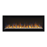
5. Place the bumpout of log #5 (W135-0764)
into the notch on the top of log #3. Ensure the
other end rests on the lower part of the media
tray. Do not cover any burner ports.
6. Place the bumpout of log #6 (W135-0765) into
the notch on the left side of log #2. Ensure the
other end rests on the lower part of the media
tray. Do not cover any burner ports.
A2
A1
Stud
Pilot Shield
Air Cover
Stud
Burner Ports
Burner Pan
Lower Part of Media Tray
Bottom Cutout
A1
A2
1
1
2
1
2
Bumpout
Notch
3
1
2
3
4
Bumpout
Notch
1
2
3
4
Bumpout
Notch
5
A2
A1
Stud
Pilot Shield
Air Cover
Stud
Burner Ports
Burner Pan
Lower Part of Media Tray
Bottom Cutout
A1
A2
1
1
2
1
2
Bumpout
Notch
3
1
2
3
4
Bumpout
Notch
1
2
3
4
Bumpout
Notch
1
2
3
4
5
6
Bumpout
Notch
A2
A1
Stud
Pilot Shield
Air Cover
Stud
Burner Ports
Burner Pan
Lower Part of Media Tray
Bottom Cutout
A1
A2
1
1
2
1
2
Bumpout
Notch
3
1
2
3
4
Bumpout
Notch
1
2
3
4
Bumpout
Notch
1
2
3
4
5
6
Bumpout
Notch
5
Air Cover
A2
A1
Stud
Pilot Shield
Air Cover
Stud
Burner Ports
Burner Pan
Lower Part of Media Tray
Bottom Cutout
A1
A2
1
1
2
1
2
Bumpout
Notch
3
1
2
3
4
Bumpout
Notch
1
2
3
4
Bumpout
Notch
1
2
3
4
5
6
Bumpout
Notch
5
Air Cover
 Loading...