14
INSTALLING DECODERS
Read the following section on decoders before starting. There are shortcuts to temporary
installations of the other components, but do not shortcut the decoder. We recommend
you get your first decoder installed by a dealer or locomotive manufacturer just so you
have a good example of how it’s done.
The most important part of a successful decoder installation is proper isolation of
both
motor brushes from the track so that they are driven only by the decoder. Failure to
isolate will definitely damage the decoder. Damage caused by failure to isolate the motor
is not covered by the guarantee or warranty.
We find it preferable to mount the decoder with 1/2" wide 3M photo-mount double sided
foam tape (we get ours at the local supermarket).
Before test running your newly converted locomotive on full power double check your
wiring to make sure the motor is fully isolated and that there are no pinched or broken
wires. We see many decoders returned due to wires getting pinched between the body
shell and frame causing shorts.
Due to the high in-rush current of incandescent grain-of-wheat type bulbs (about 10
times the normal operating current) we have rated the decoder function outputs at
100mA each. We recommend Miniatronics part number 18-014-10 (2.4mm diameter 14
volt/30mA) bulbs for good results. If you are running higher voltages you will need to use
16 or 18 volt bulbs.
If you need to use higher current lamps (50-150mA) we recommend a 22 ohm 1/4 Watt
resistor in series with each bulb (this will also greatly extend bulb life). The function
outputs are rated at 150mA continuous if used with LEDs or other low in-rush devices.
Always make sure the motor is isolated from the frame. Always make sure metal
couplers are isolated from the frame.
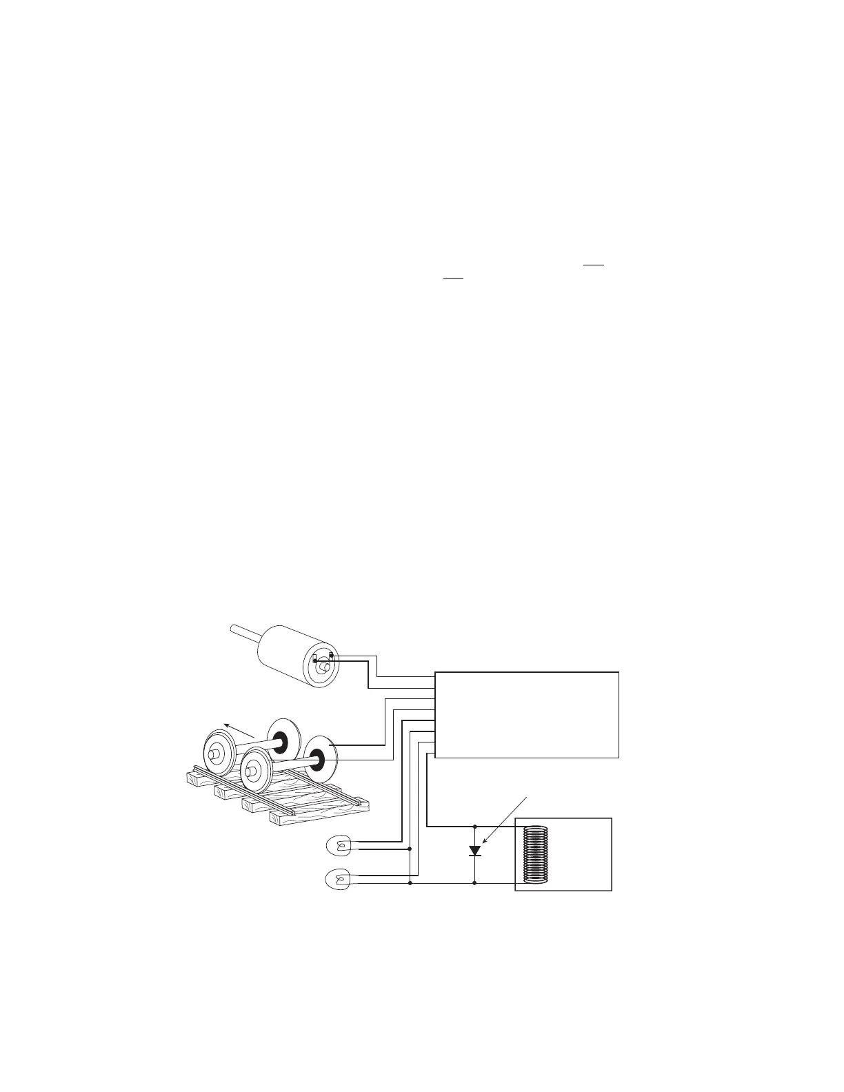
Note 1: The function common (blue wire) is the positive lead providing rectified DC voltage. If you
elect to NOT use the common, power the light or other device from either track power pickup for
half-wave operation (approx. 1/2 voltage).
Relay, Smoke
unit, etc.
-
+
Note: If a function controlled device presents
inductive load (such as a relay), always use
a suppression diode (such as 1N4004 or 1N914)
across the device.
Motor -
Motor +
Right Track Power Pickup
Left Track Power Pickup
Forward Light
Light or Function Common (see note 1)
Reverse Light
Function 1 (not on all decoders)
Gray
Orange
Red
Black
White
Blue
Yellow
Green
Blue
Left Rail
Firemans Side
Right Rail
Engineers Side
Motor
WARNING: To prevent decoder damage,
ALWAYS make sure the motor brushes are
properly isolated before applying power.
Forward