22
in daisy chain fashion. Use the 4-wire RJ-H cable for this purpose. Longer cables may be
used if more distance is needed between power stations. The last power station at the
end of the daisy chain will have one empty socket. The booster will place a nominal
10mA load on the command station control bus. In an emergency you can use a
telephone handset cord to connect the control bus.
STATUS LIGHT
This light will illuminate steadily under normal operations. Flashing indicates an abnormal
or fault condition. Here is a description of the various conditions indicated by the status
light.
Steady on - Track power is on and operations are normal.
Rapid flash - No DCC signal from command station (control bus cable is unplugged,
programming track in use, etc.).
Slower steady flash - Short Circuit (over current shutdown). The booster will shut down
for 2-3 seconds or until the short or load of over 5.1 Amps is removed.
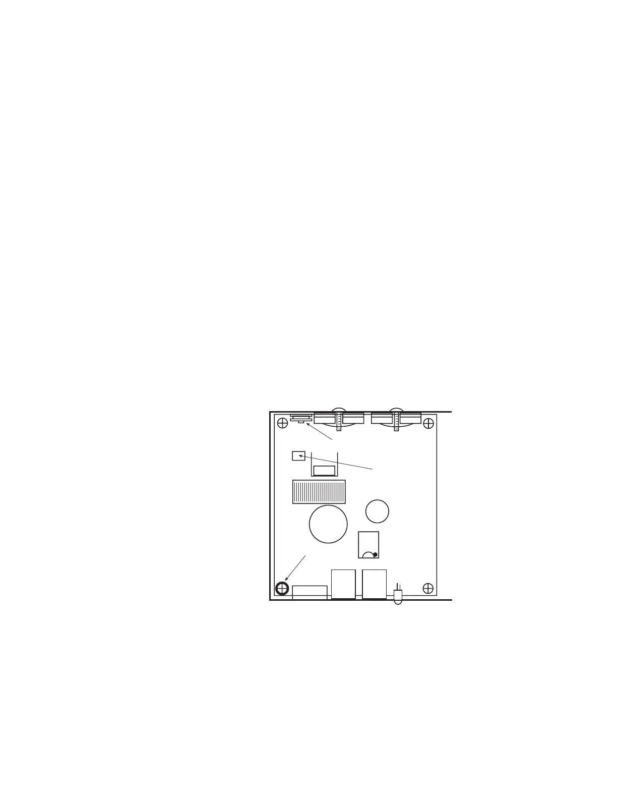
PB105 and PB110A TRACK VOLTAGE ADJUSTMENT
The track voltage is adjustable from 9.5 to 18 volts. Adjustment requires opening the
case of the booster and turning the blue adjustment potentiometer as shown below.
Adjusting the PB105 DCC output voltage:
1) Set voltmeter to DC volts.
2) Touch minus (black) lead of meter to the indicated mounting screw at YY.
3) Touch plus (red) lead of meter to the rectangular silver circuit board pad marked
VREG.
4) Turn DCC voltage adjustment pot to desired output voltage.
5) Adjust all boosters to the same
voltage. Otherwise you will see
a speed variation when you
cross power district
boundaries.
NOTE 1: Adjust the voltage with
no appreciable load on track.
The output voltage will rise
slightly as more current is
drawn to compensate for the
drop in the output MOSFETs
and associated wiring.
NOTE 2: If you have a means of
measuring the track voltage (a
typical “True RMS” reading
meter will NOT be able to read
the track voltage) the voltage
can be adjusted through a
hole in the back of the PB105
chassis without opening the
cover.
NOTE 3: We do not recommend
setting the track voltage above
16 volts. Voltage that high is
very hard on any lights you
may have installed in
locomotives.
DCC voltage
adjustment pot
VREG (+)
measurement
location
GROUND (-)
YY