23
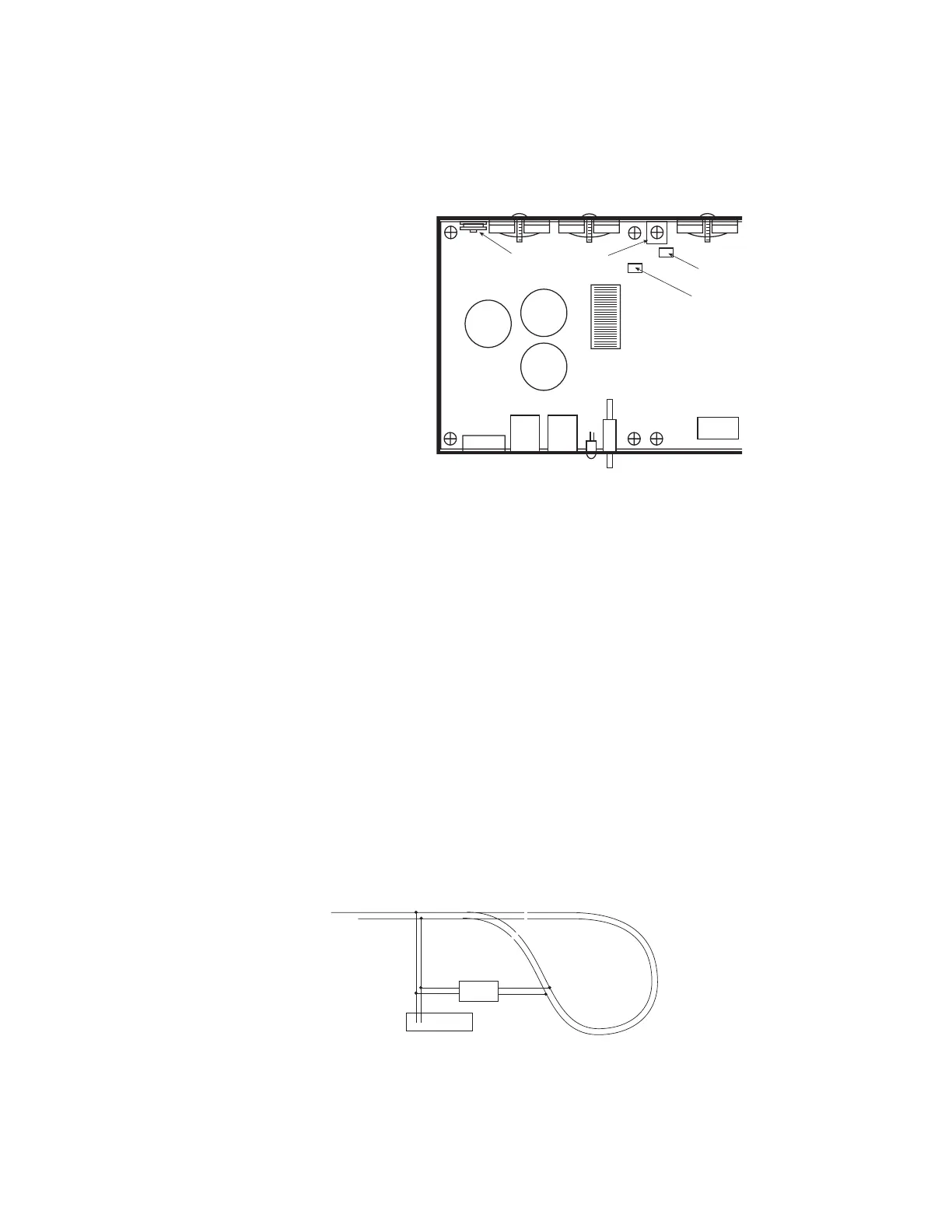
Adjusting the PB110A DCC Ouput Voltage
1) Set voltmeter to DC volts.
2) Touch minus (black) lead of
meter to the indicated
GROUND pad.
3) Touch plus (red) lead of
meter to the rectangular
silver circuit board pad
marked VREG.
4) Turn DCC voltage
adjustment pot to desired
output voltage.
5) Adjust all boosters to the
same voltage. Otherwise
you will see a speed
variation when you cross
power district boundaries.
NOTE 1: Adjust the voltage
with no appreciable load
on track. The output
voltage will rise slightly as
more current is drawn to compensate for the drop in the output MOSFETs and
associated wiring.
NOTE 2: If you have a means of measuring the track voltage (a typical “True RMS”
reading meter will NOT be able to read the track voltage) the voltage can be adjusted
through a hole in the back of the PB110 chassis without opening the cover.
NOTE 3: We do not recommend setting the track voltage above 18 volts. Voltage that
high is very hard on any lights you may have installed in locomotives.
USING MULTIPLE BOOSTERS ON YOUR LAYOUT
The PB105 and PB110A are supplied from the factory ready for wiring to layouts where
both rails are gapped at power district boundaries.
Double Gapped Layouts:
We recommend grounding ALL the power boosters together using wire between 18 to
24 AWG. You can use one of the cover mounting screws as the ground point on your
Power Pro system box, PB105 or PB110. This will provide the necessary current return
path for brass steam locomotives to operate across block boundaries.
Common Rail Layouts:
A simple modification is required to use multiple NCE power boosters with common rail
layouts. For the PB105 booster, take the cover off the booster and remove the screw
marked “YY” from the circuit board inside. This screw is located near the power
connector. It is the only connection from the booster circuit common to the case. The
input of the PB105 is optoisolated. For the PB110A, remove the screw from the square,
silver ground pad at the rear, middle of the circuit board.
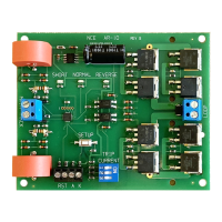
CONNECTION TO AUTOMATIC REVERSING MODULES
DCC voltage
adjustment pot
VREG (+)
measurement
location
GROUND (-)
Silver
Ground Pad
Power Pro
TRACK
Reverser