18
SYSTEM EQUIPMENT DESCRIPTIONS
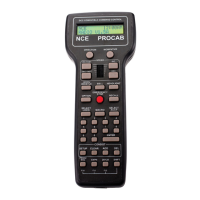
The POWER PRO
TM
System Unit (5 Amp)
The Power Pro
TM
system unit is really two separate pieces of equipment in one box. The
left half is the 5 Amp power booster (PB105) with the right half comprising the Command
Station (the brains of the system). Each half is capable of operating independently of
the other. We will first cover the Command Station portion then the PB105 power station
half.
The POWER PRO
TM
PH-10 System Units
The Power Pro
TM
PH-10 system has two main pieces of equipment. The CS02 (top)
drawing is the Command Station (the brains of the system). The PB110A (bottom
drawing) is the 10 Amp power booster. Each box is capable of operating independently
of the other. We will first cover the Command Station portion then the PB110A power
booster.
POWER PRO
FROM
NCE Corporation
DCC COMMAND STATION
STATUS TRACK
CAB BUS
CONTROL
BUS
PROGRAM
TRACK
POWER
22VAC / 30VDC MAX.
CS02
POWER PRO
FROM
NCE Corporation
DCC COMMAND STATION
with FIVE AMP POWER BOOSTER
STATUS
TRACK
22VAC / 32VDC MAX.
POWER
CONTROL BUS
POWER
PB110A
NORMAL
LOOP
POWER PRO
FROM
NCE Corporation
DCC COMMAND STATION
with FIVE AMP POWER BOOSTER
STATUS TRACK
CAB BUS
CONTROL
BUS
PROGRAM
TRACK
16VAC / 28VDC MAX.
STATUS
CONTROL BUS
22VAC / 32VDC MAX.
PH-PRO
POWER
TRACK
PB105 POWER
BOOSTER
COMMAND STATION