6
Basic Set Up of 10 Amp
Power Pro System
BE CAREFUL
The maximum input voltage to your PH-10 or PH-10R is 22 Volts AC. Voltages higher
than 22 Volts AC will ultimately destroy your booster resulting in an expensive repair
charge.
We recommend our 18V AC, 10 Amp transformer (P.N. 524-224, P1018). If you are
using a different transformer be sure to measure the actual no load voltage before
connecting it to your system.
Quick Start
Contents of the 10 Amp PH-10 System:
CS02 Command Station
PB110A Booster
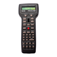
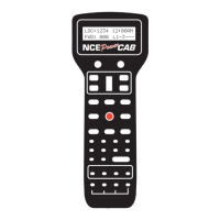
Pro Cab
Seven foot coiled cable
Twelve inch, four wire flat cable
Seven foot, four wire flat cable
UTP cab bus panel
Seven foot, six wire flat cable for the UTP panel
Power Pro system reference manual
We recommend that you follow the instructions below to connect your system to a
small test track first. After your system is checked out completely and known to be
working then consider the final installation locations for components and
connections to the track.
TRYING OUT YOUR PH-10:
#1 Disconnect the existing power supplies from your layout.
#2 Connect one end of the long (7 foot) coiled cable from the cab into the CS02 CAB
BUS socket. Plug the other end in the ProCab.
#3 We supply a twelve inch and a seven foot four wire, flat cable for the CONTROL
BUS. Depending on where you mount the CS02 and the PB110A, use either the
short or long cable. Plug one end of the cable into the CS02 CONTROL BUS
socket. The other end of this cable plugs into one of the CONTROL BUS sockets of
the PB110A. This connects the “Command Station” portion of the Power Pro to the
“Power Booster” portion.
#4 If in place, pull the 4 pin plug from its socket on the face of the Power Pro. Connect
your power source to the screw terminals marked POWER. Your power source must
have a voltage within the range of 16-22 volts AC. Follow the diagram to the left.
Make special note of the differences between the CS02 power and the PB110A
power wiring. Do not exceed these voltages as damage to the PB110A is certain to
result. If there is not enough voltage, the STATUS light on the PB110A will flash
quickly. There will be a similar indication if the DCC signal from the command
station is lost . The PB110A is factory adjusted to put out the NMRA recommended
16 volts for O and Large Scale.
NOTE: Hook up to the PB110A and the CS02 are different.