21
POWER BOOSTER
PB105 and PB110A CONNECTIONS, CONTROLS and
INDICATORS
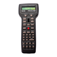
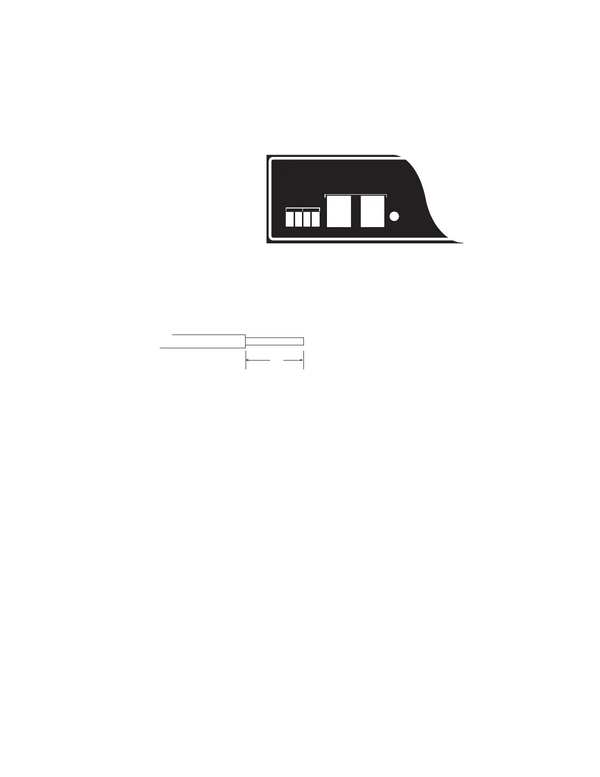
Starting at the left side of
the front panel, each
terminal, socket, and
indicator is explained
below:
POWER
TERMINALS:
Input power from an
outside power source goes
into the PB-105 via the left most two screw terminals of the four terminal black connector.
Always measure the transformer voltage before connecting it to your PB-105. A booster
that has been ‘over voltaged’ will result in catastrophic booster failure and void the
warranty (we can diagnose and determine if this has happened).
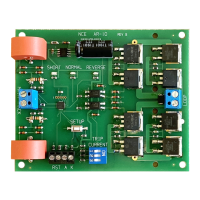
The screw terminals of the black connector are designed to accept wires up to #16 AWG
(2mm). Insulation should be stripped back
1/4 inch (6mm). Only stranded wire should
be used. If solid wire is used for track
power, make a splice joint to stranded wire
at some convenient place. Only stranded
wire should enter the terminal for reliable
contact. See the Basic Set Up of Your
System at the front of this manual.
If you wish to purchase additional connectors, you may call NCE Corporation to order
them.
THE TRACK TERMINALS:
NOTE: There are differences between the PB-105 and the PB110A boosters. See the
Basic Set Up Drawings at the front of this manual for the proper set up directions.
Wires from these terminals go to the track. If more than one booster is connected to the
layout, be sure the left track terminal on all boosters is consistently wired to the same rail.
This will ensure you have the same “phase” as you cross power district boundaries.
Always use wire of sufficient gauge (#16 minimum) to connect to the layout. Power
“drops” of #24 or #22 wire to a larger wire bus under the track are fine as long as the
length of each drop to the main bus is less than 12”.
Use of a smaller bus will prevent the booster from detecting a short circuit and may be a
fire hazard.
The voltage to the track is dependent on two factors: the power source input voltage
and the setting of the internal voltage adjustment, as discussed later. The DCC track
voltage for the Power Pro 5 Amp system is factory adjusted to the NMRA recommended
14 (+/- 0.1) volts for N, HO, and S scales. We do not recommend using a 5 Amp booster
with O-Scale as most O-Scale locomotives have stall currents in the area of 8 Amps
(Weaver, Red Caboose, P&D). For O-Scale usage we recommend our PB110A Ten Amp
power booster. The PH-10 system is factory set for 16 volts.
CONTROL BUS SOCKETS
The control bus sockets on the front of the booster are paired to allow wiring the control
signal coming from the command station to “daisy chain” through the booster. Use the
supplied cable to connect the booster to the command station’s CONTROL BUS socket.
The remaining (unused) socket on the booster can be used to connect to other boosters
POWER PRO
FROM
NCE Corporation
STATUS
CONTROL BUS
22VAC / 32VDC MAX.
POWER TRACK
16VAC / 28VDC MAX.
Insulation
Bare Stranded Wire
1/4