2-6
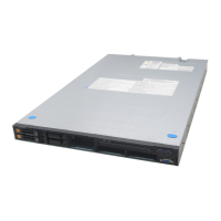
Front View (Switches and Lamps)
See Chapter 8 for detail information on lamp indication.
11 to 17 from top
5 to 10 from top
18
1 POWER switch
The power switch is used to turn on/off the power. If you WER/SLEEP lamp goes on
and the power is turned on. If you press the switch again, the power is turned off. The sy forcibly shut down when
the power switch is pressed continuously for four seconds or longer.
T switch
to reset the server.
3
e
swi
20
4 D
e the front panel and the rear panel on and off. The UID lamp
hassis and allows you to locate the server you're working on
5
Lig
in t
6
7 S
Lig
am
8
9 A
to the network. Blinking in green indicates the network activity. Numbers
10 UID
11 t
12 Pro ard error lamp
13 e
14
15
16
17
18
The he server.
19
20
ace.
21
erial interface. UPS must be connected to Serial Port A connector on the rear
front panel and the one on the rear panel are mutually exclusive.
l port B (on the rear panel) connector is the same as that of
press the switch once, then the PO
stem is
2 RESE
Th
S
e reset switch is used
L
Pr
EEP switch
ssing the sleep switch once causes the server to enter into the sleep state (power saving mode). Pressing the power
tch in the sleep state recovers the machine to the normal state. (This function is supported by Windows Server
03/Windows 2000.)
UI
P
(Unit ID) switch
r ssing the UID switch turns UID lamp (blue) located on
el is visible through the rear of the c
loc
fro
ated on the rear pan
m the rear of the serv
ers on a rack.
WER/SLEEP lamp (green)
hts in green when the server is powered on. Goes off when the server is powered off. Blinks when the system is placed
he sleep mode.
PO
ST
L
ATUS lamp (green/amber)
ig
DI
hts in green while the server is in successful operation. When any error is detected, this lamp lights or blinks in amber.
K ACCESS lamp (green/amber)
hts in green while the internal hard disk is in access. When any one of the internal hard disks fails, this lamp lights in
ber.
LA
L
N1 ACCESS lamp (green)
ig
pri
hts in green while the server is connected to the network. Blinking in green indicates the network activity. Numbers
nted near the lamps indicate the LAN port number.
N2 ACCESS lamp (gree
L
Lig
n)
hts in green while the server is connected
printed near the lamps indicate the LAN port number.
lamp (blue)
Lig
At
hts in blue when the ID switch is pressed.
ention lamp
cessor bo
M mory board error lamp
I/O
Po
board error lamp
wer supply unit error lamp
FA
Th
N error lamp
ermal error lamp
Dump switch
dump switch is used to collect the event logs having occurred in t
CL
U
EAR switch
S
s
B3 connector
device accepting the USB 1.1 interf
U
Se
ed to connect with a
rial Port B connecto
r
ed to connect with a device having a s
Us
side of the server. Serial port B on the
IMPORTANT: The shape of seria
LAN connector and ICMB connector (RJ-45). Pay attention to connect the proper cable.
1
19
2
3
20
4
21

 Loading...


