CABLE TERMINATION 6-43
Installation NWD-107460-02E
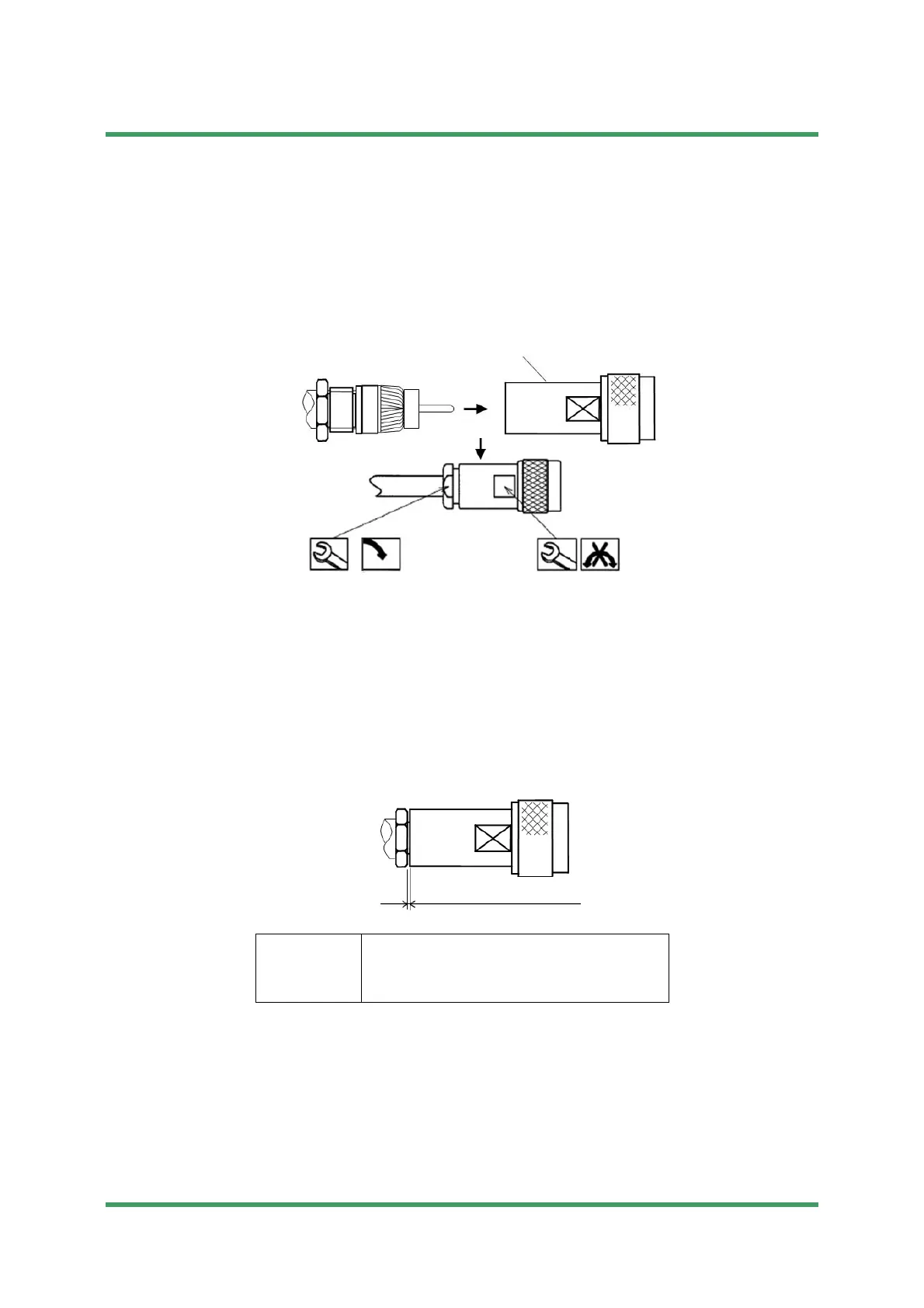
4 Connector assembly
(1) The cable center conductor must be straight and aligned with the connector
inner contact. Insert the cable into the connector body until stopped; the center
conductor must be inserted into the connector inner contact fingers. Tighten
the connection to the torque value of 9 to 11 N·m.
Notes
1. When inserting, do not put the chip which is braided wire inside the
central conductor and the connector body.
2. Do not turn connector body, turn clamp nut attachment.
(2) The gap of the connector body and clamp nut is confirmed.
(*) Gap: 0 mm
Note Do not remove the connector body tightened up once.
When removing, it is reworked from procedure 1 or a cable is
exchanged.
Tools
• spanner (16 mm)
• torque spanner (16 mm)
• clearance gauge, measure
Connector body
16 mm
9-11 N·m
16 mm
Submission Prohibited
NEC Internal Use Only
 Loading...