ANTENNA ORIENTATION 10-1
Installation NWD-107460-02E
10. ANTENNA ORIENTATION
After the initial setup has been completed, an antenna orientation will be performed
between two stations according to the following procedure .
Procedure
Apparatus
Digital Multimeter with test leads or X0818 PASOLINK Monitor Wrench
1 Connect the PC to the LCT port on the iPASOLINK IDU using LAN cable (see
Operation manual),
2 At each station, set Maintenance Control in LCT Menu,
Note In Maintenance “On” condition, every external Alarm outputs, excluding
Maintenance/PS/CPU (IDU) ALM, are masked and remote control can
not be performed.
3 Click and select for the following control items in Maintenance Control,
Notes
1. Retain the present status for other control items.
2. When the TX power control mode is set to ATPC, set it to MTPC and
required level for the PASOLINK link on the “Equipment Setup” and
“Provisioning”.
• TX SW Manual Control: Fix No.1 or No.2
(in 1+1 configuration)
• RX SW Manual Control: Fix No.1 or No.2
(which is the same side fixed by TX SW in
1+1 configuration.)
• TX Power Control: MTPC in Equipment Setup
(at opposite site) Required level in Provisioning
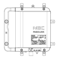
4 At receiving station, remove a cap from the RX LEV MON jack,
5 At each station connect the digital multimeter or PASOLINK Monitor to the RX
LEV MON jack on the ODU,
Submission Prohibited
NEC Internal Use Only