ISSUE 4.0 SL2100
INSTALLING THE EXPANSION INTERFACE BOARDS 79
3.3.1 Slot Location
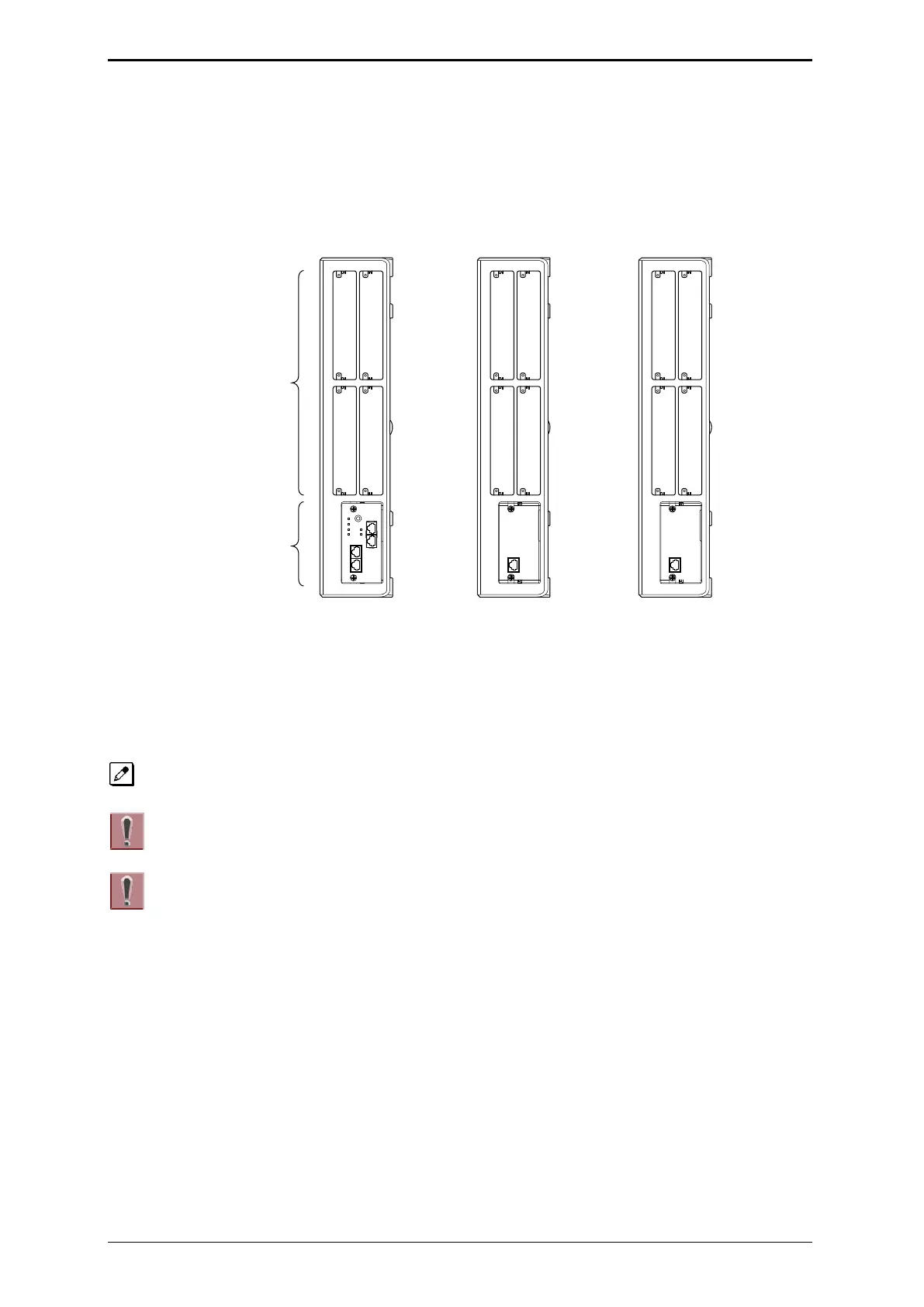
Each 4KSU-C1 has four universal slots for station, trunk and optional boards excluding CPU/EXIFE
slot. However the Slot 4,8,12 does NOT Support any types of Multiline Terminals. Analog extensions
(and any types of Trunks) shall work. The slot location in the 4KSU-C1, refer to Figure 2-58 Slot
Numbers.
Figure 2-58 Slot Numbers
3.3.2 Mounting the 082U-B1/008U-C1/000U-C1 Boards
The procedure for mounting the expansion interface boards are as follows;
The following procedure is being explained only for slot No.1. However the other slots are also the same
procedure as slot No.1.
Not all boards are hot swappable. Do not remove or install from the chassis
when powering up.
• Do Not Power on until all installation have been completed.
• If Expansion Chassis are installed, turn the power on/off in the order of Expansion 2
Chassis, Expansion 1 Chassis and then Main Chassis.
• For your safety, smooth the cut edges after removing the plastic knockout.
1. Turn off the system power.

 Loading...