1 - 6 System Map: Model A - Top View with LCD Panel Open
Quick Start Guide
1
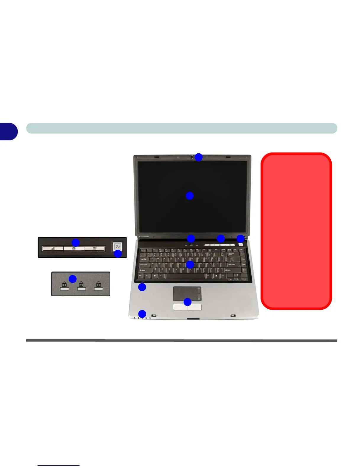
System Map: Model A - Top View with LCD Panel Open
Figure 1 - 2 - Model A - Top View with LCD Panel Open
2
4
1
6
8
3
5
9
7
1. Optional Built-In PC Camera
2. LCD
3. LED Status Indicators
4. Hot-Key Buttons
5. Power Button
6. Keyboard
7. Built-In Microphone
8. TouchPad and Buttons
9. LED Power & Communication
Indicators
4
5
3
Note: Only One Design Style is Pictured
Wireless Device
Operation Aboard
Aircraft
The use of any portable
electronic transmission de-
vices aboard aircraft is usu-
ally prohibited. Make sure
the module(s) are OFF if
you are using the computer
aboard aircraft.
Use the key combinations
to toggle power to the
WLAN/Bluetooth modules,
and check the status indi-
cator icon to see if the mod-
ules are powered on or not
(see Table 1 - 3, on page 1
- 8/Table 1 - 5, on page 1 -
10).
 Loading...