8
NESS D8 (V4.7) CONTROL PANEL – INSTALLER MANUAL
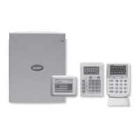
MONITORED ZONES
The Ness D8 has 10 separate monitored inputs.
• 8 x Fully programmable Zone inputs
• 2 x 24 hour Tamper input
ZONE INPUTS
Each zone input must be terminated with a 2K2 (2200
ohm) resistor as sup plied. All inputs must be sealed with
an EOL resistor even if unused.
For wiring details of Keypads, Keyswitches, Panic Buttons
and Warning devices, see the wiring diagrams in the
wiring section of this manual.
TAMP – Tamper Input
The TAMP input must also be sealed with a 2K2 end of
line resistor. This input is always a 24hr input.
AC INPUT TERMINALS
These terminals are for the connection of the Ness
plugpack. The Ness D8 re quires an AC transformer
rating of 1.4 Amps @ 17 V AC minimum. (Ness Part No.
POW215)
BATTERY
These terminals are for the connection of a sealed
lead-acid re charge a ble 12Volt battery. Charge current is
limited to 350mA. The charge voltage is factory preset
at 13.8 V and does not need changing. Note: A 12 Volt
sealed lead acid rechargeable battery must be connected
for correct panel operation. Ob serve correct Polarity when
connecting the battery.
(Ness Part Number BAT210 12V 7Ah battery)
EARTH
For maximum protection against damage caused by
lightning strikes, connect a good earth to this terminal.
Alternatively use the Earth lead from the plug pack.
PROG/TAMP – Program Link & Internal Tamper Input
The PROG/TAMP link appears on the two pin J1 header.
The PROG/TAMP link has two purposes:
1. To enter Installer Program Mode on initial
power up. Power-up with the PROG link OFF. The
PROG link (or Box Tamper lead) must be ON in
operating mode.
2. Box Tamper. When used with the Internal Tamper
Lead (supplied), PROG/TAMP serves as the
24hr tamper input for the panel’s internal tamper
switch.
Replace the PROG Link with the Box Tamper
Lead. Connect the Internal Tamper Lead spade
terminals directly to the terminals of the internal
tamper switch (supplied). An end-of-line resistor is
NOT required on this input.
When PROG/TAMP is used for Internal Tamper,
powering up with the panel’s cover open will enter
Installer Program Mode.
INPUTS
The location of the main panel housing should be
in an area that is within the pro tect ed area of the
premises. A linen closet or cupboard are good
examples as these are generally located in the centre
of the Premises.
Positioning of the movement detectors should be
considered as the incorrect position may cause
unwanted alarms.
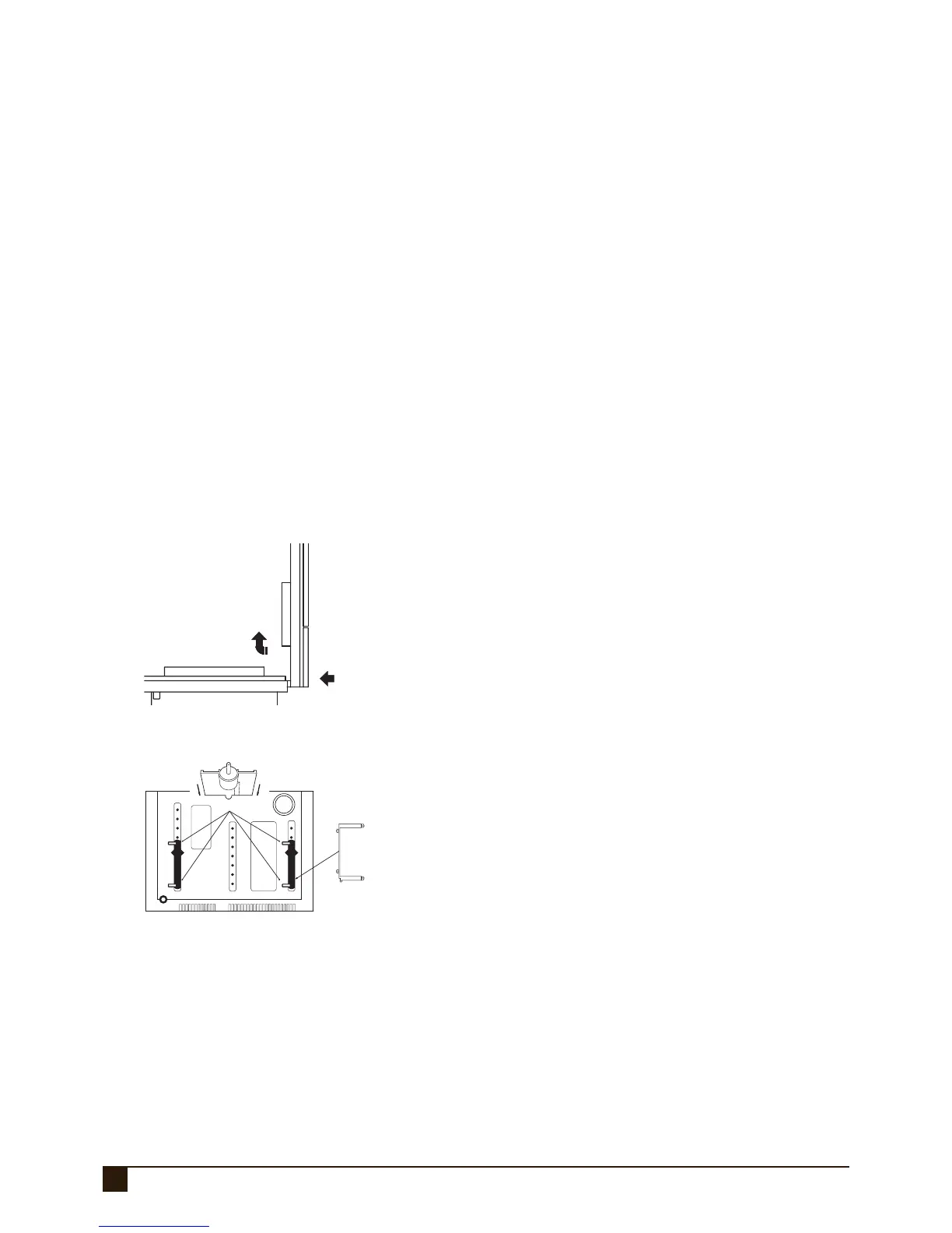
1. Unclip the lid by pushing in the directions of the arrows 1
and 2 as shown below.
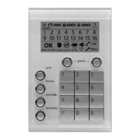
2. Remove the Battery from the base.
3. Mount the rear panel housing to a secure location.
4. Insert the PCB stand-offs in the Panel and then plug the
circuit board onto the stand-offs.
5. Wire to the circuit board terminal blocks, as per the wiring
instructions shown in this in stal la tion manual.
6. Replace the Battery.
7. Insert the panel tamper bracket as shown at left.
8. Program the control panel as required