10
NESS D8 (V4.7) CONTROL PANEL – INSTALLER MANUAL
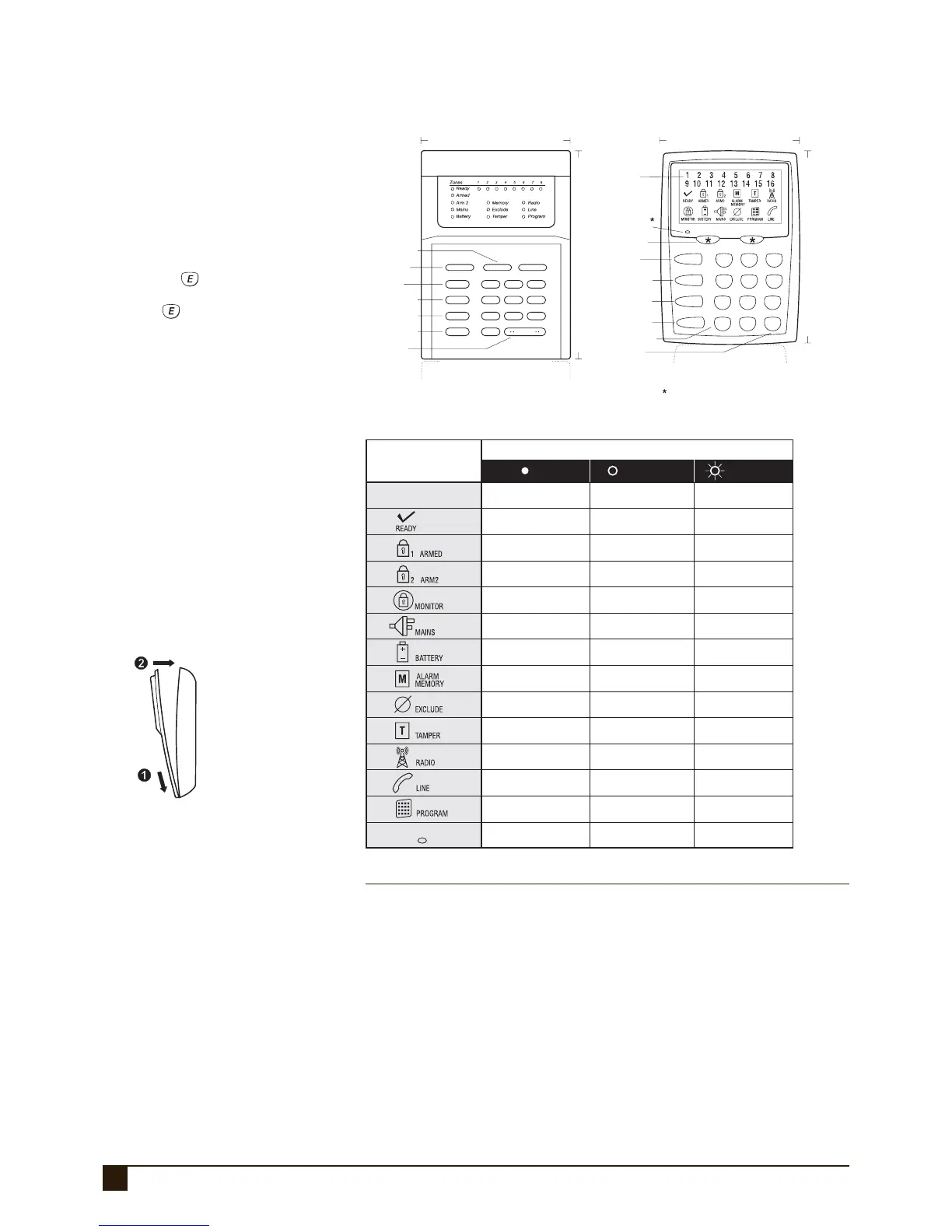
KEYPAD
2
5
8
0
1
4
7
P
3
6
9
E
ARM
MONITOR
EXCLUDE
MEMORY
Not Ready
Backlit LCD
icon display
PANIC buttons
PANIC buttons
“Not Ready” light
The “Not Ready” light is on when the panel is not ready to Arm.
i.e, a zone is unsealed, there may still be movement in the
premises or a door or window left open
ARM button
ARM button
MONITOR button
MONITOR button
EXCLUDE button
EXCLUDE button
PROGRAM button
ENTER button
MEMORY button
MEMORY button
LED KEYPAD LCD KEYPAD
PROGRAM button
Protective flap not shown
Protective flap not shown
ENTER button
PANIC
ARM
1
4
7
0
2
5
8
ENTER
3
6
9
MONITOR
EXCLUDE
PROGRAM
PANICMEMORY
105mm 90mm
150mm
135mm
D8 KEYPADS
The Ness LED or LCD keypad
provides important visual and audible
in di ca tion of the system status and
is the main interface for controlling
the many pow er ful features of the D8
system.
DISPLAY TEST (LCD KEYPAD ONLY)
To display all the keypad icons press
and hold the
button for at least
2 seconds. All the icons will be on
whilst the
button is held down.
Display Test can be activated at any
time either in operating mode or any
program mode.
NUMBER OF KEYPADS (BOTH KEYPADS)
Up to 3 LED and/or LCD keypads
can be connected to the D8.
CABLE LENGTH (BOTH KEYPADS)
The maximum allowable cable
length is 100m (total cable length to
all keypads) .
NESS D816 LCD KEYPAD (100-667)
MEMORY MODE - EVENTS INDICATED BY KEYPAD LIGHTS:
LIGHT MEMORY EVENT
Zone lights 1–8 ....................... Zone alarm
(no lights) ............................... Panel Disarmed
ARMED................................... Panel Armed (or Area 1 Armed)
ARM2 ..................................... Area 2 Armed
MAINS .................................... Mains power failure
BATTERY ................................ Low Battery
TAMPER .................................Tamper alarm (Siren cover, panel etc)
EXCLUDE ................................ Panic alarm
LINE .......................................Telephone line fail
RADIO, EXCLUDE .................... Radio Key Panic alarm
RADIO, BATTERY, ZONE .......... Radio Device battery low, (Device number is indicated by zone lights)
RADIO, BATTERY, ARM ...........Radio Key battery low, (Radio Key number is NOT indicated)
RADIO, TAMPER, ZONE ........... Radio Device tamper alarm (Device number is indicated by zone lights)
RADIO, MONITOR, ZONE ......... Radio Supervision fail (Device number is indicated by zone lights)
KEYPAD INSTALLATION
· Unclip the top half of the keypad housing
by pushing the top clips down with a small
screwdriver and pulling the housing forward.
· Screw the base of the keypad housing to the
wall using the 4 mounting holes provided.
· Bring the 4 connecting wires to the terminal
block on the PCB on the rear of the keypad
housing.
· Connect the wires to the screw terminals as
per the wiring diagram shown in this manual.
· Clip the top half onto the base by fi rst engag-
ing the bottom clips and swinging the top
closed. Push hard to ensure the clips engage.
· Attach the Zone list label on the inside of the
lid.
Zone is sealed
Zone is unsealed, or Power fault
or System is Armed,
or phone line fault
Disarmed
Disarmed
Disarmed
Normal
Normal
Normal
Normal
Normal
Normal
Normal
Normal
Ready to Arm
Zone is unsealed
Ready to Arm
Armed (AREA 1)
Armed (AREA 2)
Monitor Mode
Memory Mode selected
Receiving radio signal
Dialler is on line
Indicates that a Radio Key or
other radio device has a
low battery
Phone line fault or
failure to communicate
User Program Mode
Not ready to Arm
Zone alarm
Monitor Mode
(
LED Keypad only)
Mains Power is off
The panel’s backup
battery is low
New alarms in memory
Zones are excluded
Tamper alarm
Installer Program Mode
ZONES 1-16
Not Ready
OFF ON FLASHING
KEYPAD ICON STATUS
KEYPAD ICON
DISPLAY
NESS D8 LED KEYPAD (100-192)