MX Series Voice Gateway User Manual
New Rock Technologies, Inc. 21
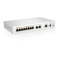
Figure 1-7 MX60 Front Panel
Table 1-12 Description of MX60 Front Panel
Each interface slot corresponds with four RJ45 sockets; each RJ45socket can correspond with
four pairs of analog lines. CAT-5 cables are used to connect the interface card and distribution
panel in equipment installation. For corresponding relations of RJ45 and RJ11, see 7 Appendix:
RJ45 and RJ11 Corresponding Relations.
Note: Numbers of interface slots vary from different configuration. Numbering definition of
interface slots: on the left side of chassis is #1 slot (marked with No.1 to 16), in the middle of
chassis is #2 slot (marked with No.17 to 32), on the right side of chassis is #3 slot (marked with
No.33 to 48).
Matrix of 4 x 4 LED status indicators on interface card. Each column of LED indicator matrix
matches four telephone lines on a RJ45. The first column on the left matches Line 1-4
respectively from top to bottom, the first column on the right matches Line 13-16 respectively
from top to bottom, and the middle columns in the same manner.
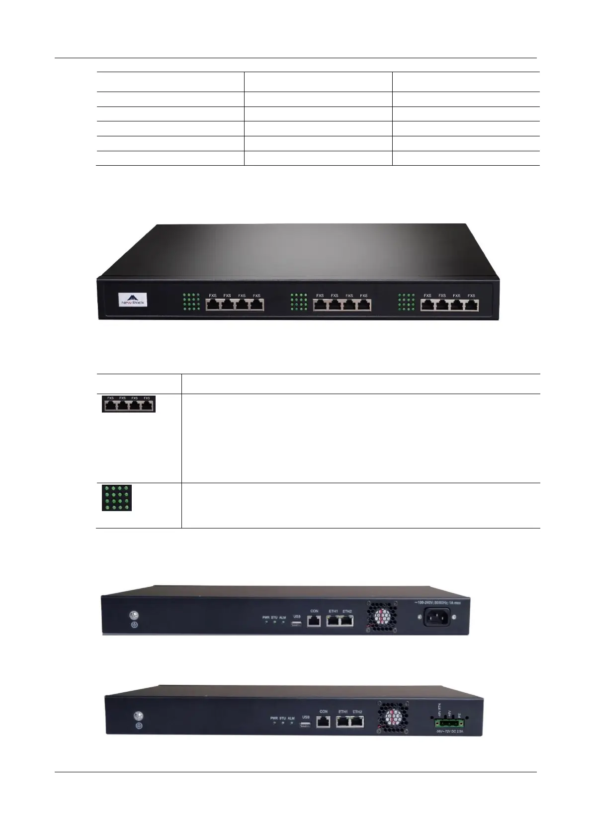
Figure 1-8 MX60 Back Panel-AC
Figure 1-9 MX60 Back Panel-DC