User Manual MX Series Voice Gateway
26 New Rock Technologies, Inc.
Four interface slots; each contains one 24-port interface card. CAT-5 cables are used to connect
the interface card and distribution panel in equipment installation. For corresponding relations of
RJ45 and RJ11, see 7 Appendix: RJ45 and RJ11 Corresponding Relations.
Numbering definition of system interface slots: on the low-left side of chassis is #1 slot (marked
with No.1 to 24), on the low-right side of chassis is #2 slot (marked with No.25 to 48), on the
up-left side of chassis is #3 slot (marked with No.49 to 72), and on the up-right side of chassis is
#4 slot (marked with No.73 to 96).
Note: The interface card is hot swappable, but you should reboot the device after the
replacement of the interface card!
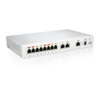
Figure 1-13 MX120G Back Panel-AC
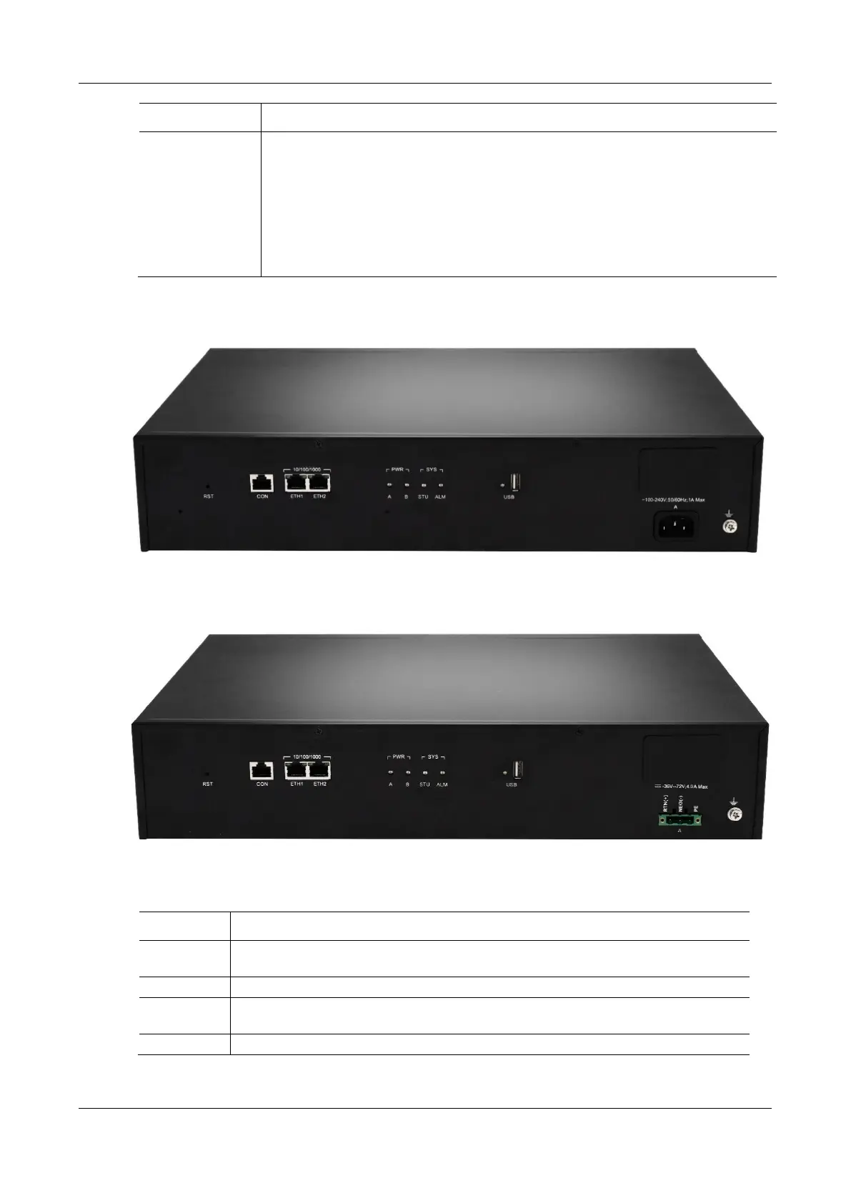
Figure 1-14 MX120G Back Panel-DC
Table 1-23 MX120G Back Panel
To restore the device to factory default, press the RST for more than 3 seconds and release it
when the STU light starts blinking in red. This setting will be valid after rebooting the device.
Configuration interface (CON), used for local management and debugging.
Two 10/100 Mbps Ethernet ports (RJ45). They share one IP address, which by default is
192.168.2.240 and you can change it on Basic > Network page.