Satellite Terminal Components
User Manual for the Satellite Terminal
version 3.0
3
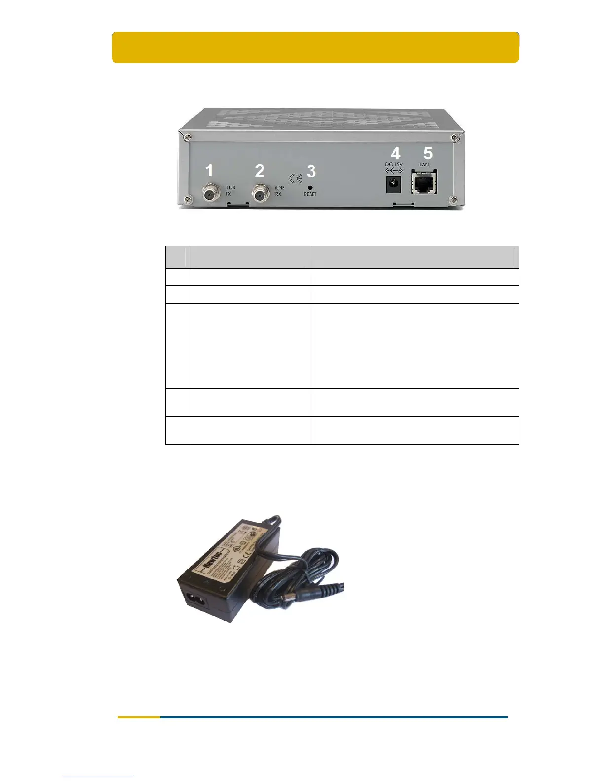
2.1.2 The IPmodem Back Panel
Figure 2 – The IPmodem Back Panel
Nr What Description
1 Tx connector Indoor connection for the transmit coax cable.
2 Rx connector Indoor connection for the receive coax cable.
3 Reset button
Reboot: press once briefly (hold less than 5
seconds);
Factory Reset: press and hold for more than 5
seconds.
Resetting will also reboot the terminal and
change all the IP-settings back to the default
factory settings.
4
15V power cable
connector
Power connector (5.5/2.5mm plug).
5 Ethernet cable connector
Connection for the LAN, type RJ-45 (Ethernet
cable).
Table 2 - Description of the Elements on the IPmodem Back Panel
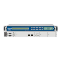
2.1.3 The Power Supply
Figure 3 - IPmodem Power Supply
Universal input range: nominal 100 – 240 Volt / 50 – 60 Hz;
NEMA - IEC320/C8 socket;
CE approved;