Do you have a question about the Newtec MDM9000 and is the answer not in the manual?
Declares conformity with EU Radio and Telecommunication Terminal Equipment Directive 1995/5/EC.
Provides relevant EMC information related to FCC rules for digital devices.
Outlines environmental conditions to avoid for safe operation and cleaning instructions.
Details the importance and connection of the rear panel earth ground terminal.
Describes Newtec's support services packages for equipment protection and technical assistance.
Explains the meaning of caution, hint, and reference symbols used in the manual.
Highlights innovative elements improving efficiency and lowering Total Cost of Ownership.
Discusses FlexACM® technology for adaptive modulation and Automatic Uplink Power Control.
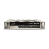
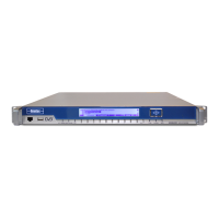
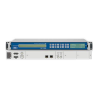
Details the components of the front panel, including display, buttons, and indicators.
Describes the meaning and behavior of the device's LED status indicators.
Details the power connector, safety precautions, and power supply specifications.
Describes the SUBD 9 pin connector for CLI management over RS232.
Details protocols for data insertion, including GSE, XPE, MPE, and ULE.
Lists possible hardware options for RF signal transmission.
Explains how the carrier arriving from the satellite is taken in.
Guides on configuring the device's management IP address and saving it as a boot configuration.
Describes loading templates for a back-to-back connection between two MDM9000 devices.
Details loading templates for FlexACM enabled Layer 3 connections.
Describes the web application for remote device management, configuration, and monitoring.
Details how to manage the device using CLI via Ethernet or craft interface.
Describes managing device configurations, including saving, loading, and importing.
Outlines the procedure for upgrading device software.
Explains the importance of redundancy and integration with USS switches.
Explains configuration of Data1 and Data2 Ethernet ports for IP traffic.
Describes the block handling Baseband Frames received on data Ethernet ports.
Describes the modulator functional block for performing actual modulation.
Explains the demodulator functional block for performing demodulation.
Describes Newtec's FlexACM technology for adaptive modulation and coding.
Explains automated uplink power control to compensate for fading.
Lists general device and interface alarms.
Details general demodulator alarms.
Details DVB standards: DVB-S2, DVB-S2X, and S2 Extensions.
Explains the Es/No parameter for transmission quality and its relation to PER.
Provides an overview of frequently used Layer 2 expressions for packet filtering.
Explains the basic expression "all" for capturing all incoming packets.
Provides an overview of frequently used Layer 3 expressions for IP packet filtering.
Explains the basic L3 expression "ip4 dst net 0.0.0.0/0" to capture all IPv4 packets.
Describes the GSE packet header fields and GSE label types for filtering.
Details supported modulation schemes and FEC.
Details L-BAND connector, frequency, level, return loss, and spurious performance.
Details connector, return loss, power levels, frequency, and adjacent signal specifications.
Provides threshold Es/No values for DVB-S2 with normal frames and pilots off.
Provides threshold Es/No values for DVB-S2X with normal frames and pilots off.
Presents performance tables for bandwidth cancellation in symmetrical links.
Provides an overview of back panel combinations for Module 1.
Lists ordering options and figures for mains power supply units.
| Modulation | QPSK, 8PSK, 16APSK, 32APSK |
|---|---|
| Power Supply | 100 - 240 VAC, 50/60 Hz |
| Operating Temperature | 0°C to +50°C |
| Frequency Range | 950 MHz to 2150 MHz |
| FEC | DVB-S2, DVB-S2X |
| Data Rate | up to 425 Mbps |
| Dimensions | 19" rack mount, 1U high |