Newtec Proprietary
Confidentiality: Unrestricted
R3.2_v1.0
278/387
Feature Descriptions
MDM9000 Satellite Modem
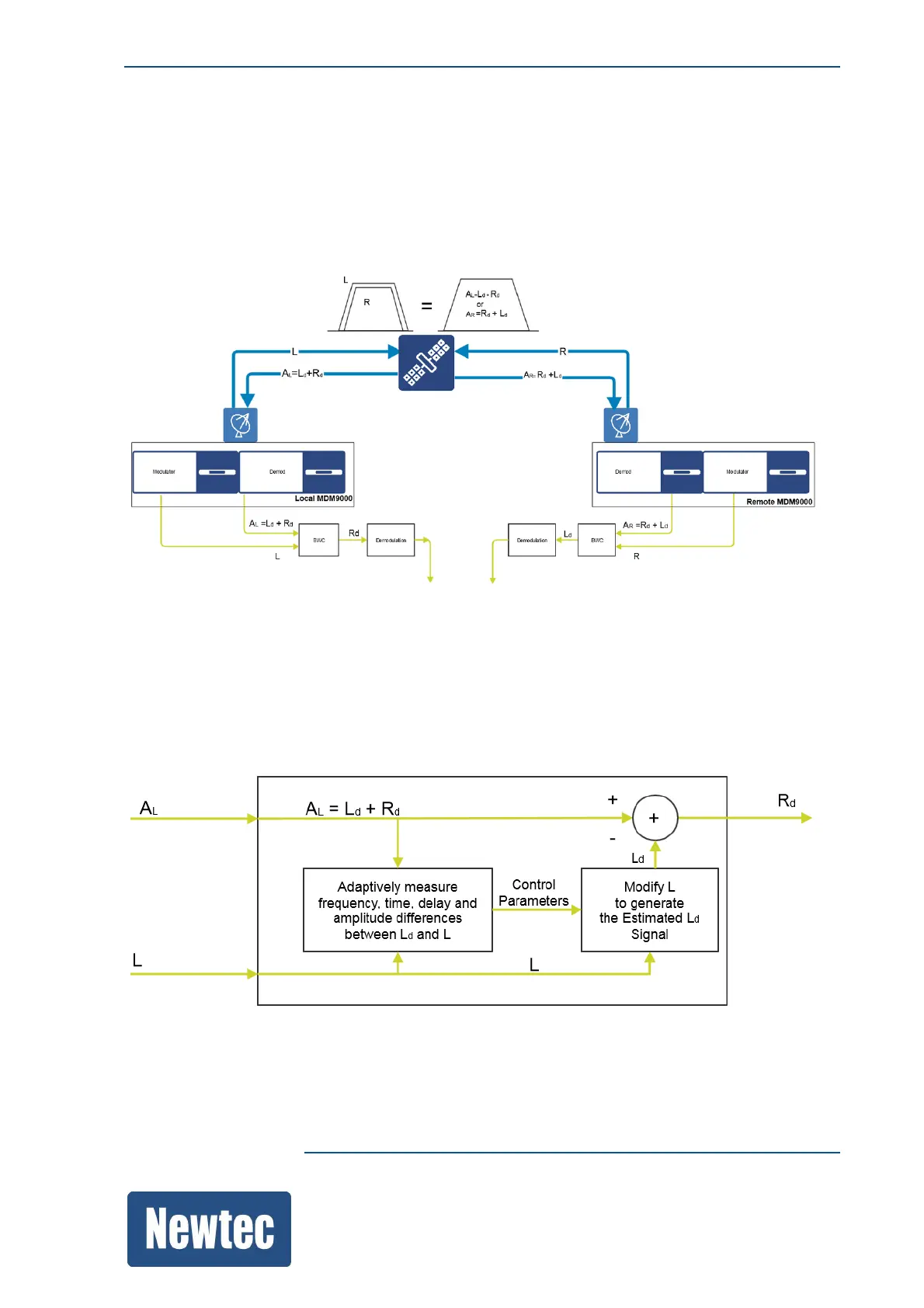
16.16.1 Block Diagram
The following figure depicts a point-to-point bandwidth cancellation link where the carriers from the
"Local" and "Remote" modem overlap.
The “Local” modem uplinks a signal L and receives an aggregate signal AL that consists of the
desired signal Rd from the “Remote” modem and its own uplinked signal Ld (with d indicating that
the signal has a satellite delay).
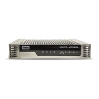
The BWC function (depicted in the following figure) receives a copy of the uplinked signal L and the
received signal AL = Rd + Ld. Both signals are used to determine the amplitude, frequency and time
shift the uplink signal experienced when passing over the satellite link.
With this information a signal Ld is generated. This signal Ld is subtracted from the aggregate
received signal AL. The output is the desired signal Rd, the signal coming from the remote modem
which is then demodulated.