Newtec Proprietary
Confidentiality: Unrestricted
R3.2_v1.0
35/387
Block Diagram
MDM9000 Satellite Modem
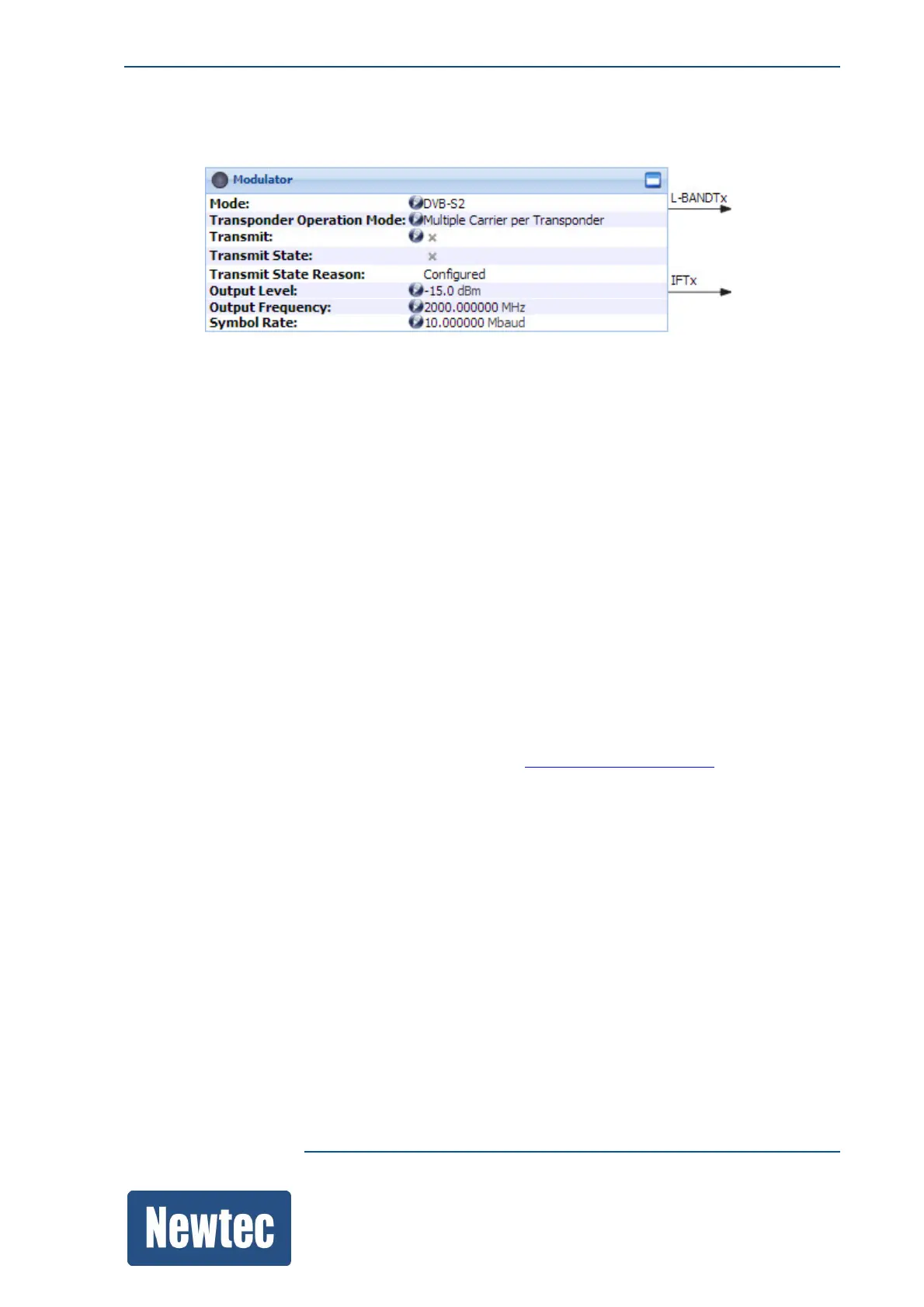
10.5 Modulator
The modulator takes in the BBFs and applies the selected modulation mode.
The following parameters are set in this block:
• DVB-S2 or DVB-S2X or S2 Extensions
• Transmit
• Output Level
• Output Frequency
• Symbol Rate
• ...
After modulation, the signal is made available on either the L-band or IF-output
(depending on the device configuration).
10.5.1 PRBS Generator
The modem provides a build-in PRBS (Pseudo-Random Binary Sequence) generator. Use the
generator to perform basic tests on the device and/or check the satellite link conditions.
The Test LED on the front panel and in the status bar of the GUI is green when the PRBS generator
is activated. For more information please refer to section: PRBSGenerator.onpage181
10.5.2 L-band TX or IF-band TX Interfaces
Depending on the ordered hardware and software, the following data output interfaces are available.
• An L-BAND TX or IF-BAND TX output is used for the transmission of RF signals.
The possible options are:
• L-BAND with switchable 10 MHz output (950-150 MHz) ordering nr. OU-00.
• IF-BAND (50-80 MHz) ordering nr. OU-01.
• IF + L-band with switchable 10 MHz output, ordering nr. OU-02.
It is possible to multiplex a 10 MHz reference signal on the L-band interface for an outdoor BUC
(Block UP Converter).
• L-band with switchable 10 MHz output and 24/48 V DC BUC power (on the L-band only),
ordering nr. OU-05.
• IF + L-band with switchable 10 MHz output and 24/48 V DC BUC power (on the L-band only),
ordering nr. OU-06.