Doc# E107706 12- 1
Electro Industries/GaugeTech
The Leader In Power Monitoring and Smart Grid Solutions
12: Flicker and Analysis
12: Flicker and Analysis
12.1: Overview
Flicker is the sensation that is experienced by the human visual system when it is
subjected to changes occurring in the illumination intensity of light sources. The
primary effects of Flicker are headaches, irritability and, sometimes, epileptic
seizures.
IEC 61000-4-15 and former IEC 868 describe the methods used to determine Flicker
severity. This phenomenon is strictly related to the sensitivity and the reaction of indi-
viduals. It can only be studied on a statistical basis by setting up suitable experiments
among people.
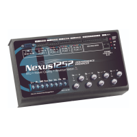
The Nexus® 1250/1252 meter with V-1 (base configuration) offers Flicker monitoring
and analysis. The Nexus® 1252 meter with V-2 has EN50160/IEC61000-4-30 Power
Quality Compliance analysis for Flicker and other power quality measurements. (Refer
to the V-Switch™ key information in Chapter 2.) Refer to Chapter 23 in the Communi-
cator EXT
TM
4.0 and MeterManager EXT Software EXT User Manual for additional infor-
mation.
12.2: Theory of Operation
Flicker can be caused by voltage variations that are in turn caused by variable loads,
such as arc furnaces, laser printers and microwave ovens. In order to model the eye
brain change, which is a complex physiological process, the signal from the power
network has to be processed while conforming with Figure 12.1, shown on page 12-4.
• Block 1 consists of scaling circuitry and an automatic gain control function that nor-
malizes input voltages to Blocks 2, 3 and 4. For the specified 50 Hz operation, the
voltage standard is 230 V RMS.
• Block 2 recovers the voltage fluctuation by squaring the input voltage scaled to the
reference level. This simulates the behavior of a lamp.
• Block 3 is composed of a cascade of two filters and a measuring range selector. In
this implementation, a log classifier covers the full scale in use so the gain selection
is automatic and not shown here. The first filter eliminates the DC component and
the double mains frequency components of the demodulated output. The configura-
 Loading...