Doc# E107706 2 - 3
2: Meter Overview
Electro Industries/GaugeTech
The Leader In Power Monitoring and Smart Grid Solutions
Electro Industries/GaugeTech
The Leader In Power Monitoring and Smart Grid Solutions
• Freeze Commands: Freeze, Freeze/No-Ack, Freeze with Time, Freeze with
Time/No-Ack.
• Freeze with Time Commands enable the Nexus® meter to have internal time-
driven Frozen and Frozen Event data. When the Nexus® meter receives the Time
and Interval, the data is created.
For complete details, download the appropriate DNP User Manual from our website
www.electroind.com.
2.3: Flicker
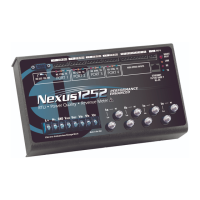
A Nexus® 1252 with V-1 (base configuration) provides Flicker Evaluation in
Instantaneous, Short Term and Long Term Forms. A Nexus® 1252 meter with
V-Switch
TM
key 2 provides EN50160 / EN61000-4-30 Power Quality Compliance. See
Chapter 12 for a detailed explanation of the Flicker and Power Quality Compliance
functions.
2.4: INP2 Internal Modem with Dial-in/Dial-out Option
The following sections describe the optional INP2 Internal Modem.
2.4.1: Hardware Overview
The INP2 Option for the Nexus® 1250/1252 meter provides a direct connection to a
standard telephone line. No additional hardware is required to establish a communica-
tion connection between the meter and a remote computer. The RJ11 Jack is on the
face of the meter. A standard telephone RJ11 plug can connect the meter to a stan-
dard PSTN (Public Switched Telephone Network).
The modem operates at up to 56k baud. It supports both incoming calls (from a
remote computer) and automatic dial-out calls when a defined event must be auto-
matically reported. With the device configured with the INP2 Option, the meter has
dial-in capability and provides remote access to other Modbus-based serial devices via
the meter’s RS485 Gateway over your phone line. The meter recognizes and responds
to a Modbus Address of 1. With any other address, the command passes through the
gateway and become a virtual connection between the remote Modbus master and
any Modbus slave connected to the RS485 Gateway.