Doc# E107706 4- 5
Electro Industries/GaugeTech
The Leader In Power Monitoring and Smart Grid Solutions
4: Electrical Installation
4.2: Wiring the Monitored Inputs and Voltages
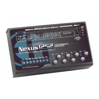
Select a wiring diagram from Section 4.9 that best suits your application. Wire the
Nexus® 1250/1252 meter exactly as shown. For proper operation, the voltage con-
nection must be maintained and must correspond to the correct terminal. Program
the CT and PT Ratios in the Device Profile section of the Communicator EXT
TM
soft-
ware; see the Communicator EXT
TM
4.0 and MeterManager EXT Software User Manual
for details.
The cable required to terminate the voltage sense circuit should have an insulation
rating greater than 600V AC and a current rating greater than 0.1 Amp.
Use a minimum of 14 AWG wire for all phase voltage and current connections.
The maximum installation torque for both the current input terminals and the voltage
connections is 1 Newton-Meter.
4.3: Fusing the Voltage Connections
For accuracy of the readings and for protection, EIG requires using 0.25-Amp rated
fuses on all voltage inputs as shown in the wiring diagrams (see Section 4.9).
The Nexus® 1250/1252 meter can handle a maximum voltage of 150V phase to neu-
tral and 300V phase to phase. Potential Transformers (PTs) are required for higher
voltages with the standard rating. With Option G, the direct voltage input is extended
to 300V phase to neutral and 600V phase to phase.
NOTE: Option G is only intended for use with direct connections. For PT connections,
use the standard 150 Volt version.
4.4: Wiring the Monitored Inputs - VRef
The Voltage Reference connection references the monitor to ground or neutral.
4.5: Wiring the Monitored Inputs - VAux
The Voltage Auxiliary connection is an auxiliary voltage input that can be used for any
desired purpose, such as monitoring neutral to ground voltage or monitoring two
different lines on a switch. The VAux Voltage rating is the same as the metering Volt-
age input connections.
4.6: Wiring the Monitored Inputs - Currents
Install the cables for the current at 600V AC minimum insulation. The cable connector
should be rated at 10 Amps or greater and have a cross-sectional area of 14 AWG.


 To Next Page