Doc# E107706 5 - 13
5: Communication Wiring
Electro Industries/GaugeTech
The Leader In Power Monitoring and Smart Grid Solutions
Electro Industries/GaugeTech
The Leader In Power Monitoring and Smart Grid Solutions
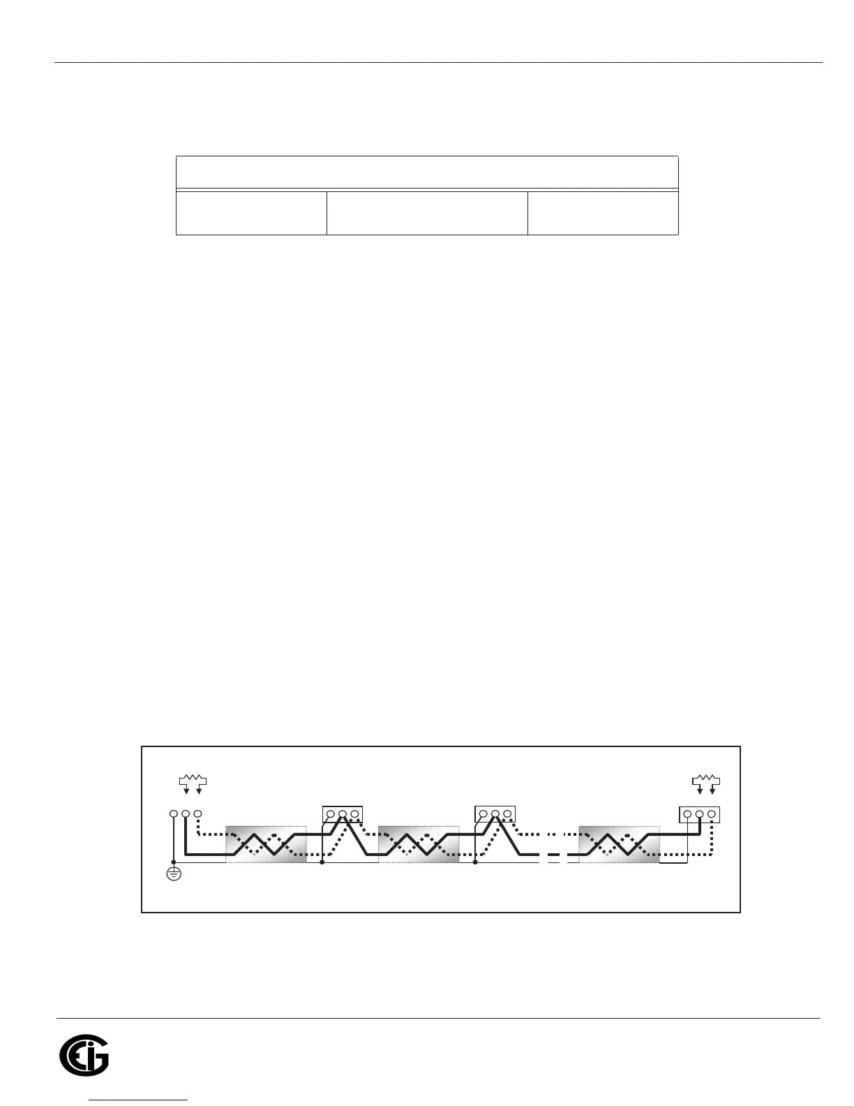
5.7: Linking Multiple Nexus® Meters in Series
You may connect a total of 31 Nexus® meters in series on a single bus using RS485.
The cable length may not exceed 4000 feet (1219 meters). Before assembling the
bus, each Nexus® meter must be assigned a unique address. See Chapter 13 in the
Communicator EXT
TM
4.0 and MeterManager EXT Software User Manual for instruc-
tions.
• Connect the + and - terminals of each Nexus® meter. Use jumpers on any RS485
Master connected at the end of the chain.
• Connect the shield to the (S) terminal on each Nexus® meter and to the Ground on
the RS485 Master. This connection is used to reference the Nexus® meter’s port to
the same potential as the source. It is not an earth-ground connection. You must
also connect the shield to earth-ground at one point. Vous devez égale-
ment connecter l’écran à la terre à un moment donné.
• Provide termination resistors at each end, connected to the (+) and (-) lines. RT is
approximately 120 Ohms, but this value may vary based on length of cable run,
gauge or the impedance of the wire. See RT EXPLANATION in Section 5.3 .
Figure 5.9: Linking Multiple Nexus® Meters in Series
Table 2:
Nexus® Display VA Ratings
P41N+/P41N+/
P43N+
LED Displays 8VA
Twisted pair, shielded (SH) cable
R
T
+ - SH
R
T
+ - SH
+ - SH
+ - SH
Slave device 1
Slave device 2
Last Slave device N Master device
Earth Connection, preferably at
single location
Twisted pair, shielded (SH) cable Twisted pair, shielded (SH) cable