Doc# E107706 5 - 9
5: Communication Wiring
Electro Industries/GaugeTech
The Leader In Power Monitoring and Smart Grid Solutions
Electro Industries/GaugeTech
The Leader In Power Monitoring and Smart Grid Solutions
The Unicom 2500 can be configured for either 4-
wire or 2-wire RS485 connections. Since the
Nexus® meter uses a 2-wire connection, you
need to add jumper wires to convert the Unicom
2500 to the 2-wire configuration.
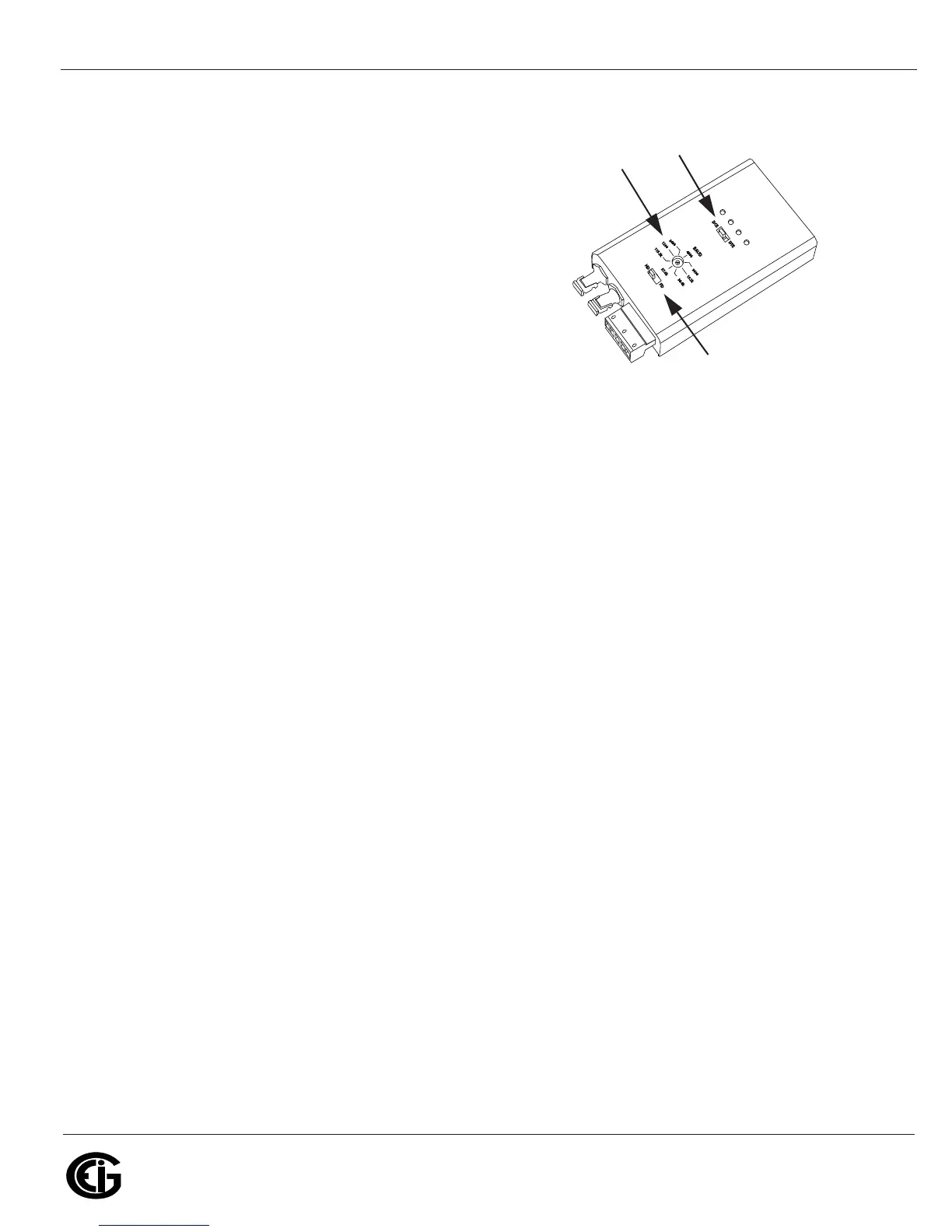
As shown in Figure 5.7, you connect the "RX-"
and "TX-" terminals with a jumper wire to make
the "-" terminal, and connect the "RX+" and
"TX+" terminals with a jumper wire to make the
"+" terminal. See the figure on the right for the
Unicom 2500’s settings. The Unicom’s Baud rate
must match the Baud rate of the meter’s RS485 port: you set the Baud rate by turn-
ing the screw to point at the rate you want.
5.3.4: RS485 Connection to the Nexus® P40N+ External Display
Insert one end of the supplied RS485 cable into Port 3 of the Nexus® 1250/1252
meter. Port 3 is factory-set to match the Nexus® display’s baud rate of 9600. To use a
port other than Port 3, you must set the port’s baud rate to 9600 using the
Communicator EXT
TM
software (see Chapter 13 of the Communicator EXT
TM
4.0 and
MeterManager EXT Software User Manual for instructions). Insert the other end of the
cable into the back of the Nexus® P40N/P40N/+, P41N+ or P43N+ display. (The con-
nectors fit only one way into the ports.)
The cable harness brings 17V DC to the displays from the Nexus® meter. RS485
communication is viable for up to 4000 feet (1219 meters). If your cable length
exceeds 200 feet you must use a remote power supply, such as EIG’s PSIO, and:
1. Connect the shield to the shield (S) terminal on the Nexus® display port. The (S)
terminal on the Nexus® meter is used to reference the Nexus® meter’s port to the
same potential as the source. It is not an earth-ground connection. You must also
connect the shield to earth-ground at one point. Vous devez également
connecter l’écran à la terre à un moment donné.
2. Provide termination resistors at each end, connected to the + and - lines. RT is
approximately 120 Ohms. See RT EXPLANATION in Section 5.3.
v
Set switch
to DCE
Set the
Baud rate
Set switch
to FD