Doc# E107706 4- 8
Electro Industries/GaugeTech
The Leader In Power Monitoring and Smart Grid Solutions
4: Electrical Installation
• Do not ground the unit through the negative of the DC supply. Separate ground-
ing is required.
• Externally fuse the power supply with a 5 Amp @250V rated slow blow fuse. EIG
recommends that you fuse both the L+ and N- connections for increased safety,
but if you are fusing only one connection, fuse the L+ connection.
• Use at least 14 Gauge supply wire for the power supply and ground connections.
NOTE ON CORRECT METER FUNCTIONING:
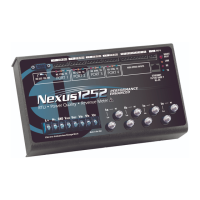
The Nexus® 1250/1252 meter has a Heartbeat LED, located on the top, right side of
the meter face. When the meter is functioning correctly, the red LED pulse toggles on
and off (blinks) 5 times per second. If the meter is not functioning correctly, the
Heartbeat LED slows to one pulse per second
4.9: Wiring Diagrams
Choose the diagram that best suits your application. Diagrams appear on the follow-
ing pages. If the connection diagram you need is not shown, contact EIG for a custom
Connection diagram.
NOTE: If you purchased a "G" Option Nexus® 1250/1252 meter for a 300 Volt
secondary, be sure to enable the option on the CT and PT screen of the Communicator
EXT
TM
software's Device Profile (see Chapter 13 of the Communicator EXT
TM
4.0 and
MeterManager EXT Software User Manual for instructions). Do not use the “G” option
with PTs. It is intended for direct Voltage connection, only.
Table 2:
Control
Power
Option
Suffix
18-60 Volts
DC
D
90-276
Volts AC/
DC
D2