Doc# E107706 13- 3
Electro Industries/GaugeTech
The Leader In Power Monitoring and Smart Grid Solutions
13: Substation Rack Mount Assembly
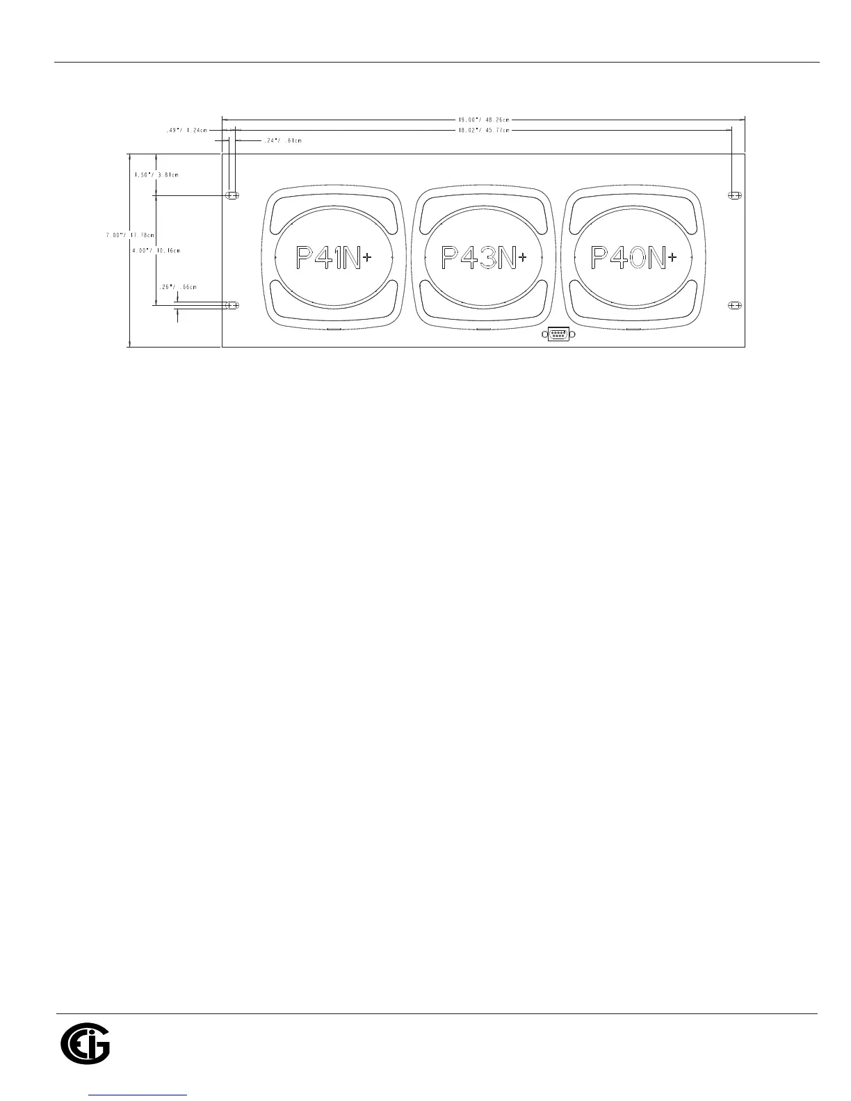
Figure 13.2: Rack Assembly Dimensions
13.6: Wiring
The voltage and current signals from the potential and current transformers should be
connected to the Test switch (see Figure 13.4). There are positions for voltage and
current phases A, B, and C, Neutral voltage, and DC Power supply. The Test switches
are labeled for easy wiring.
Please follow the Nexus® 1252 meter wiring diagrams concerning proper connections
(see Section 4.9).
13.7: Ordering Information
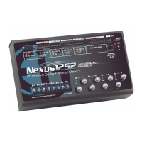
The rack assembly ordering code is 4RU3DSP. It is placed at the end of the Nexus®
1252 meter order, for example:
1252-A-120-D-60-V1-X-X-4RU3DSP
which translates to a Nexus® 1252 meter with Advanced memory, 120 Input Voltage
option, D Power Supply option, 60Hz, V-Switch
TM
key 1, no expansion port, no Reve-
nue Seal, and in the rack assembly.


 To Next Page